If you get into more complicated PCB design, you’ll find the need to drill tiny and accurate holes much more often. Wouldn’t it be nice to have a precise way of doing that? Maybe even something as simple as strapping a $10 USB digital microscope to it?
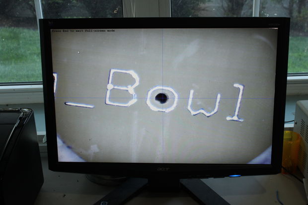
That was [mlerman’s] thought anyway, and from the looks of it, it seems to work quite well! If you already have a PCB drill press then it’s just a matter of installing the microscope opposite the drill — align it to the center point with some cross hairs and boom you’re in business.
But if you don’t yet have a PCB drill, [mlerman’s] got you covered there too, as he explains in great detail how to modify a cheap drill press into an inverted PCB drill press.
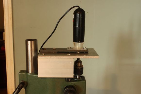
Wait, why is it inverted? Besides making more room for the USB microscope to sit, it also ensures the microscope lens doesn’t get covered in the PCB fairy dust that would fall on it if it were in a normal orientation.
[via Embedded-Lab]


The source material states “USB Microscope – I am using a Digimicro unit purchased on eBay for $28.00 USD, but any similar one should work. “. So the $10 figure used in this article is misleading. It isn’t wrong though as surprisingly good USB scopes can be had for $10.
runout; no microscope can fix that.
But maybe a bungee cord can.
My cheap Chinese drill press has a lot of what I guess you’d call runout. Lots of slop. Once any force is applied to the bit – even a tiny carbide bit – the spindle tends to move off the previous center. The holes end up in the wrong places, and bits frequently get snapped. There’s an adjustment which is supposed to resolve this, but it starts binding the spindle before it adequately reduces the problem.
To drill precision holes, I attach a tensioned bungee cord to a non-rotating part of the spindle, in such a way that it pulls the spindle sideways. As long as the force from the bungee is significantly more than the force applied to the bit while drilling, the spindle remains in a stable position.
what a really nice, simple solution. There’s no reason this couldn’t scale up to larger projects where precise hole location and speed are critical
When I first glanced at the picture, I thought, WOW! that monitor is working even with a bullet hole in the middle of it!
These were my thoughts exactly…
And the winner for this weeks convoluted Rube Goldberg award goes to this hack, for making the simple process of drilling a hole where you need it into an up-side-down adventure.
Commercial manual PCB drill machines (from back when that type of thing was done) drill upwards, typically using a foot pedal to actuate the quill, and use a crosshair scope on top to align the board. This project is a great implementation of that effective concept.
Mounting the spindle upside down certainly works for ensuring good visibility under the camera.
However, if you have compressed air in the shop, it is better to mount a tiny air nozzle to the drill stand. Using reduced pressure, just enough to gently blow away the fresh chips. This is no more messy than an upside-down spindle and has the advantage that lubrication can still be applied and the drill setup remains usable for other work than PCB milling.
I did a similar setup 2 years ago: http://vimeo.com/44367481
It has the advantage that you can aim nearly perfect and then drill the hole.
If you drill down as usual, you have an optical problem with the aiming because you watch the drill from the side. You also tend to move the pcb in the last moment to correct the position and break the tiny drills while doing that.
Anyway, all my last projects were completely SMD :-)
If the camera is in a fixed angle to the workpiece you’re trying to drill from above, you can simply clamp the workpiece down, drill a hole, and put a post-it note corner on the spot where the hole appears on the monitor.
1. Get a Proxxon FBS240 + Proxxon MB140
2. Get the job done
what a really cool, simple solution