The Clapper™ is a miracle of the 1980s, turning lights and TVs on and off with the simple clap of the hands, and engraving itself into the collective human unconsciousness with a little jingle that implores – nay, commands – you to Clap On! and Clap Off! [Rutuvij] and [Ayush] bought a clap switch kit, but like so many kits, this one was impossible to understand; building the circuit was out of the question, let alone understanding the circuit. To help [Rutuvij] and [Ayush] out, [Rafale] made his own version of the circuit, and figured out a way to explain how the circuit works.
While not the most important component, the most obvious component inside a Clapper is a microphone. [Rafale] is using a small electret microphone connected to an amplifier block, in this case a single transistor.
The signal from the microphone is then sent to the part of the circuit that will turn a load on and off. For this, a bistable multivibrator was used, or as it’s called in the world of digital logic and Minecraft circuits, an S-R flip-flop. This flip-flop needs two inputs; one to store the value and another to erase the stored value. For that, it’s two more transistors. The first time the circuit senses a clap, it stores the value in the flip-flop. The next time a clap is sensed, the circuit is reset.
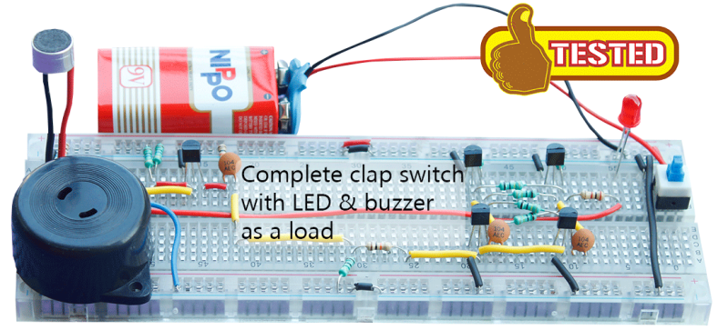
Output is as simple as a LED and a buzzer, but once you have that, connecting a relay is a piece of cake. That’s the complete circuit of a clapper using five transistors, something that just can’t be done with other builds centered around a 555 timer chip.


link please?
Found it: http://rafalerobotics.in/clap-switch/
It seems like Rutuvij and Ayush are two kids and the explaining is not done by them, but by a guy named Rafale.
“…simple as a LED and a buzzer, but one[sic] you have that, connecting a relay…”
Shouldn’t that read ‘once’ ?
“something that just can’t be done with other builds centered around a 555 timer chip.”
Shure it can be done with a 555. Inside a 555 there is an R-S flipflop and 2 comparators. Here a schematic of a clap switch done with a CMOS version of 555 timer namely TLC555.
https://drive.google.com/file/d/0BxigE4DTzAg_ZTdGV0FfdDNLcFk/view
The working principle is to move the trigger point near the [THRES] or [TRIG] depending on the state of [OUT] pin.
R2 and R3 in parrallel with R4+R5 form a voltage divider when [OUT] is high the voltage will be just below 2/3 Vdd when [OUT] is low it will be just above 1/3 Vdd. A clap sound near microphone should be enough to generate a peak voltage that would set the comparator which trigger point is nearest to that of voltage divider.
C2 is a low pass filter as we don’t want the voltage divider to follow the audio frequencies.
Although I didn’t test it, I’m confident that it would works. At worst it could need a single transistor to amplify the microphone output.
> “something that just can’t be done with other builds centered around a 555 timer chip,”
> That’s the complete circuit of a clapper using five transistors
> The 555 has ~= 25 transistors
> For the next layout update we’re adding greentext
So what’s the point? Nobody is interested in the number of transistors inside an IC. We’re just interested in usefullness and cost. But I agree the circuit is a good teaching tool.
Okay, I’m just going to say it…. the real beauty of The Clapper is that it takes TWO closely spaced claps to make it turn on/off the device. That eliminates massive quantities of false triggers. I appreciate the effort here, but it’s just not very practical.
Today, I’ll be that guy….
I’m sure you can take a couple of pills to get rid of it…
I’d like to see the schematic from the kit that was “impossible to understand”
http://pdfpiw.uspto.gov/.piw?docid=05493618&PageNum=1&&IDKey=639F013B2011&HomeUrl=http://patft.uspto.gov/netacgi/nph-Parser?Sect1=PTO1%2526Sect2=HITOFF%2526d=PALL%2526p=1%2526u=%25252Fnetahtml%25252FPTO%25252Fsrchnum.htm%2526r=1%2526f=G%2526l=50%2526s1=5493618.PN.%2526OS=PN/5493618%2526RS=PN/5493618
Mid-80’s a shipmate had a Clapper connecting his VCR and TV.
He called it his F**k Alarm.
Every time he played an action movie some character would invariably utter the inflected expletive, which word would then be sensed by the Clapper, which would then shut down his entire movie watching experience.