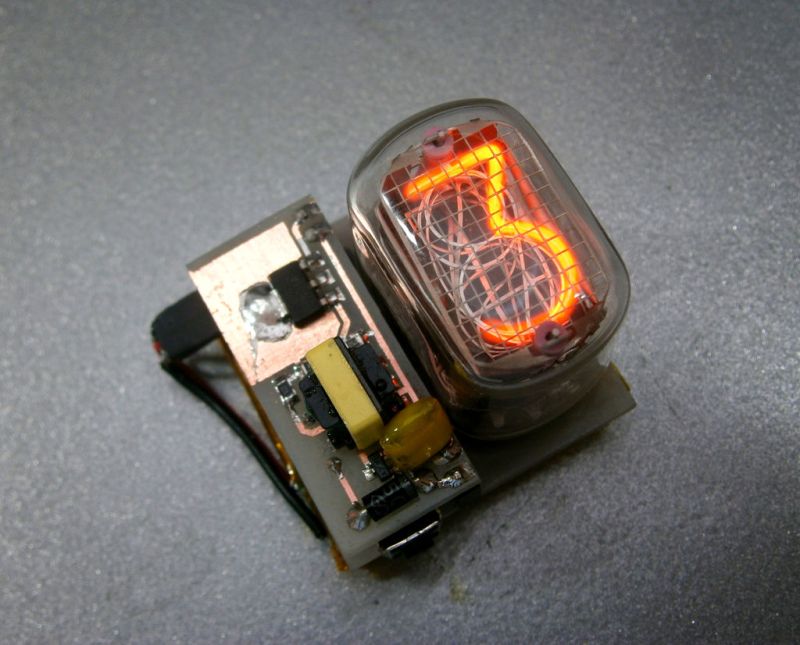
We’ve seen a few Nixie projects around here before, but this one might be the simplest yet. [Pinomelean] designed this simple nixie tube clock with just a handful of components.
The Nixie tube chosen for the project is an IN-12a. This tube can be purchased for around just four dollars. It is capable of displaying one digit at a time, zero through nine. Since the tube can only display one digit at a time, the clock is programmed to flash each digit of the current time one by one. There is a longer pause in between each cycle to make it easier to tell when the cycle begins and ends.
The system is broken into two main components. The first is the clock circuit. The clock runs off a PIC microcontroller with a 4MHz crystal. All of the logic is performed via the PIC and only a handful of other components are required. This includes some resistors and capacitors as well as a few high voltage SMD transistors to control the Nixie tube. [Pinomelean] has made this PCB design available so anyone can download it and make their own clock.
The second component to the clock is the power supply. The system is powered by a lithium-ion rechargeable battery, but [Pinomelean] notes that it can also be powered with USB. The lower voltage works well for the microcontroller, but the Nixie tube needs a higher voltage. [Pinomelean] built his own high voltage supply using components scavenged from an old disposable camera. This power supply board design is also made available for download, but it plugs into the main board so you can use another design if desired.. Check out the demo video below to see it in action.


Very nice, judging from the watch either a European hacker or a ham. Also this clock is begging to be made into a watch, I just don’t know how fragile the tube would be in a watch configuration and he’ed have to change the time display to only come on at the press of a button to save the battery. Great work.
Or military. Or a scientist. There are plenty of situations in the U.S. where 24-hour clocks are used. Kinda like with the metric system.
Cute clock! It’s funny how at some point (in the video, see around 0:42), he obviously realized the high voltage converter was getting too hot, and so he went and applied some additional heat sinking. I have to say, that converter seems like quite a horrible design, first downconverting from 5V to 1.5V with an LDO to then upconvert to 200V or so. Every step adds additional inefficiencies. Removing the LM317 would probably also work and make it generate less heat. Probably the 5V was obtained through another regulator :(. Also, he’s handling these high voltages with his bare hands, which can be dangerous.
Yes, the power supply is highly inefficient, but as i said in the instructable, it was from a disposable camera.
i could have designed a proper supply and make it more efficient, but i prefered to use what i already had.
Also, note that the whole supply is in a separate board, so anyone building the clock can plug there their own hv supply board. This design is open for modifications and improvements.
You made it a watch? Could you write , what parts were used in the high voltage generator ? It names . It is very necessary .
i sn’t touching 200V quite dangerous?
At low enough current, naaah. At sufficient current to drive such a project as this, maybe. Great thing about electricity, it does a remarkable job at sorting out those who would work with it!
I had a project that involved quite a few camera flash circuits. I have probably been shocked by their fully charged caps a few dozen times. It is unpleasant but not really harmful.
OMG he is touching High Voltage! DAAANGER!!!!