nixieclock

Simple And Elegant Single Digit Nixie Tube Clock

We’ve seen a few Nixie projects around here before, but this one might be the simplest yet. [Pinomelean] designed this simple nixie tube clock with just a handful of components.

The Nixie tube chosen for the project is an IN-12a. This tube can be purchased for around just four dollars. It is capable of displaying one digit at a time, zero through nine. Since the tube can only display one digit at a time, the clock is programmed to flash each digit of the current time one by one. There is a longer pause in between each cycle to make it easier to tell when the cycle begins and ends.

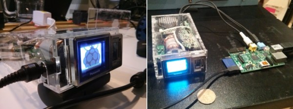
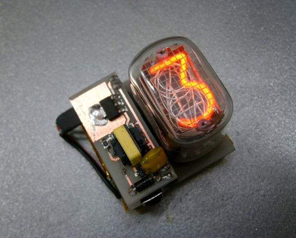
The system is broken into two main components. The first is the clock circuit. The clock runs off a PIC microcontroller with a 4MHz crystal. All of the logic is performed via the PIC and only a handful of other components are required. This includes some resistors and capacitors as well as a few high voltage SMD transistors to control the Nixie tube. [Pinomelean] has made this PCB design available so anyone can download it and make their own clock.

The second component to the clock is the power supply. The system is powered by a lithium-ion rechargeable battery, but [Pinomelean] notes that it can also be powered with USB. The lower voltage works well for the microcontroller, but the Nixie tube needs a higher voltage. [Pinomelean] built his own high voltage supply using components scavenged from an old disposable camera. This power supply board design is also made available for download, but it plugs into the main board so you can use another design if desired.. Check out the demo video below to see it in action. Continue reading “Simple And Elegant Single Digit Nixie Tube Clock”

1.37″ CRT Restored By Hacklab For Miniature MAME Cabinet

For $5, [William] of Toronto’s Hacklab hackerspace got a hold of one of the smallest CRT screens ever made – about the size of a large coin. Over the course of a couple sessions – including a public hack boothside at their Mini Makerfaire – [William], [Igor], and several other members managed to connect it as a monitor directly off a Raspberry Pi. The end-goal is the world’s smallest MAME cabinet (smaller by almost half than this LCD one).

As Canada followed the US and stopped broadcasting analog back in 2011, it became quite a challenge to feed the screen a video source. They disclosed early that the easiest solution would just be an RF transmitter on the Pi and then tune the micro-set to that channel. Too easy. They wanted something elegant and challenging so they went digging into the circuitry to find a place to insert a composite video signal directly.

The real story here is their persistence at reverse engineering. The PCB was folded like a cardboard box to fit in the original case, making large portions of the circuitboard and wiring inaccessible. Even when they managed to trace the signal to what they thought was the appropriate chip (marked C80580), they could not find any information on the 30 year old chip. Noting that every other chip on the board was Panasonic and started with “AN5”, [Igor] suspected the mystery silicon was just renamed and went through every single datasheet he could find with that prefix. Combined with form factor, pin count and purpose, his sleuthing was rewarded with a guess for a match – the AN5715. His hunch was correct – using that datasheet led him to the answers they required.

Then they just had to figure out how get the composite signal the Pi outputted into something the chip would use to display the correct image. There were no shortage of challenges, failures and dead ends here either, but they had help from the rest of their membership.

Their project log is an interesting narrative through the process and in the end of course, it worked. It is displayed beautifully with a clear acrylic case and ready for a cabinet to be built.

laser keyboard

MIDI Keyboard With Frickin’ Laser Keys

MIDI instruments are cool, but they’re not laser cool. That is, unless you’ve added lasers to your MIDI instrument like [Lasse].

[Lasse] started out with an old MIDI keyboard. The plan was to recycle an older keyboard rather than have to purchase something new. In this case, the team used an ESi Keycontrol 49. They keyboard was torn apart to get to the creamy center circuit boards. [Lasse] says that most MIDI keyboards come withe a MIDI controller board and the actual key control board.

Once the key controller board was identified, [Lasse] needed to figure out how to actually trigger the keys without the physical keyboard in place. He did this by shorting out different pads while the keyboard was hooked up to the computer. If he hit the correct pads, a note would play. Simple, but effective.

The housing for the project is made out of wood. Holes were drilled in one piece to mount 12 laser diodes. That number is not arbitrary. Those familiar with music theory will know that there are 12 notes in an octave. The lasers were powered via the 5V source from USB. The lasers were then aimed at another piece of wood.

Holes were drilled in this second piece wherever the lasers hit. Simple photo resistors were mounted here. The only other components needed for each laser sensor were a resistor and a transistor. This simple discreet circuit is enough to simulate a key press when the laser beam is broken. No programming or microcontrollers required. Check out the demonstration video below to see how it works. Continue reading “MIDI Keyboard With Frickin’ Laser Keys”

Tripping On Oscilloshrooms With An Analog Scope

This might be an old trick, but it’s still cool to see a functional tool like the oscilloscope manipulated for an unrelated purpose such as this. [Jerobeam Fenderson] made a video explaining how to input stereo audio into an old digital scope in order to create of all things, dancing mushrooms… because why not?

In this case, [Jerobeam] used a Tektronix D11 5103N set in X Y mode and attached the left and right channels from his RME Fireface UC audio interface. One channel corresponds with X, and the other with Y. From here, he controls the wave forms discretely with the help of software like Pure Data (Pd) and Max (not free, but more powerful) which are visual programming environments made to enable musicians and artists to create software without writing lines of code. His video explains how to make a circle out of a sine wave, and then beat the crap out of it with math far beyond our comprehension. The outcome is pretty mesmerizing and leaves us wanting to try it out ourselves. Luckily, if you’re interested in experimenting with the voice of sine waves… [Jerobeam] has more information on his blog on how to do some scope play of your own whether your hardware is analog or digital.

You can see the dancing mushrooms in his video below:

Continue reading “Tripping On Oscilloshrooms With An Analog Scope”

Logic Simulator Atanua Goes Free, Possibly Open Source

The history of software is littered with developers that built a great product, gave people a reasonable option to license the software, and ended up making a pittance. There’s a reason you don’t see shareware these days – nobody pays. It looks like [Gates] had a point with his Open Letter to Hobbyists.

Such is the case with Atanua. [Jari] built a nice little graphical logic simulator that has tens of thousands of downloads, and is being used in dozens of universities. [Jari] has sold only about 60 licenses for Atanua, netting him only a few thousand Euro. You can’t develop software with a pittance, so now [Jari] is giving Atanua away. This neat little logic simulator has reached the end of its life, the license is free, and [Jari] is out of the business.

This isn’t an ideal situation, but [Jari] is strongly considering open-sourcing Atanua. The code is a little bit of a mess at the moment, and cleaning it up will require a bit of work. [Jari] is leaving the option to buy a license for Atanua open, and anyone who wants to see this bit of software open sourced could buy a license or hundred.

While this isn’t great news for [Jari], if you’re looking for a neat tool to learn digital logic, you now have a very nice free option. Atanua simulates individual logic gates, 74-series chips, and even an 8051 microcontroller in real-time (up to about 1 kHz), with enough buttons, LEDs, and displays to do some very cool stuff. It’s more than enough to learn digital logic on, and good enough for a test bed for some odd and bizarre projects you might have floating around your head.

3D Printed Lens

3D Printed Lenses Open Up Possibilities

Now this is some seriously cool stuff. The folks over at FormLabs decided to try a little experiment to test the optical clarity of their clear resin. It’s pretty damn clear.

Using their own slicing software, PreForm, [Craig Broady] printed the lens piece in an orientation that would maximize resin flow around the lens to help prevent defects, keeping it as smooth as possible. While the printed part looks quite clear, all lenses require some form of polishing to become optically clear. It was printed with a 50 micron resolution, and [Craig] used a power drill to sand the lens down from 220 grit to 2000 grit sand paper.

Continue reading “3D Printed Lenses Open Up Possibilities”

Desk lamp

Sleek Desk Lamp Changes Colors Based On Sun Position

[Connor] was working on a project for his college manufacturing class when he came up with the idea for this sleek desk lamp. As a college student, he’s not fond of having his papers glowing brightly in front of him at night. This lamp takes care of the problem by adjusting the color temperature based on the position of the sun. It also contains a capacitive touch sensor to adjust the brightness without the need for buttons with moving parts.

The base is made from two sheets of aluminum and a bar of aluminum. These were cut and milled to the final shape. [Connor] found a nice DC barrel jack from Jameco that fits nicely with this design. The head of the lamp was made from another piece of aluminum bar stock. All of the aluminum pieces are held together with brass screws.

A slot was milled out of the bottom of the head-piece to make room for an LED strip and a piece of 1/8″ acrylic. This piece of acrylic acts as a light diffuser.  Another piece of acrylic was cut and added to the bottom of the base of the lamp. This makes for a nice glowing outline around the bottom that gives it an almost futuristic look.

The capacitive touch sensor is a pretty simple circuit. [Connor] used the Arduino capacitive touch sensor library to make his life a bit easier. The electronic circuit really only requires a single resistor between two Arduino pins. One of the pins is also attached to the aluminum body of the lamp. Now simply touching the lamp body allows [Connor] to adjust the brightness of the lamp.

[Connor] ended up using an Electric Imp to track the sun. The Imp uses the wunderground API to connect to the weather site and track the sun’s location. In the earlier parts of the day, the LED colors are cooler and have more blues. In the evening when the sun is setting or has already set, the lights turn more red and warm. This is easier on the eyes when you are hunched over your desk studying for your next exam. The end result is not only functional, but also looks like something you might find at that fancy gadget store in your local shopping mall.