You’ve seen CMOS logic, you’ve seen diode-resistor logic, you’ve seen logic based on relays, and some of you who can actually read have heard about rod logic. [Julian] has just invented optoisolator logic. He has proposed two reasons why this hasn’t been done before: either [Julian] is exceedingly clever, or optoisolator logic is a very stupid idea. It might just be the former.
Inside each optoisolator is a LED and a phototransistor. There’s no electrical connection between the two devices, which is exactly what you need in something that’s called an isolator. [Julian] was playing around with some optoisolators one day to create a weird push-pull circuit; the emitter of one phototransistor was connected to the collector of another. Tying the other ends of the phototransistor to +5V and Gnd meant he could switch between VCC and VDD, with every other part of the circuit isolated. This idea whirled around his mind for a few months until he got the idea of connecting even more LEDs to the inputs of the optoisolators. He could then connect the inputs of the isolators to +5V and Gnd because of the voltage drop of four LEDs.
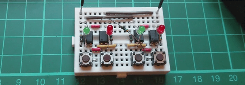
A few more wheels turned in [Julian]’s head, and he decided to connect a switch between the two optoisolators. Connecting the ‘input’ of the circuit to ground made the LED connected to +5V light up. Connecting the input of the circuit to +5 made the LED connected to ground light up. And deeper down the rabbit hole goes [Julian].
With a few more buttons and LEDs, [Julian] created something that is either an AND, NAND, OR NOR, depending on your point of view. He already has an inverter and a few dozen more optoisolators coming from China.
It is theoretically possible to build something that could be called a computer with this, but that would do the unique properties of this circuit a disservice. In addition to a basic “1” and “0” logic state, these gates can also be configured for a tri-state input and output. This is huge; there are only two universal gates when you’re only dealing with 1s and 0s. There are about 20 universal logic gates if you can deal with a two.
It’s not a ternary computer yet (although we have seen those), but it is very cool and most probably not stupid.
Video below.


So with a DLP chip you could build the world’s weirdest fpga?
Optoisolated FPGA actually sounds like a slow compared to digital switching but neat idea.
You could… But not unless you’ve read up on how to load data into a DLP chip and drive it (it’s hard!)
Do you know of any resources where I can read up on this?
http://www.ti.com/lit/ug/dlpu002a/dlpu002a.pdf is a start.
TI has a ton of resources online.
After an admittedly quick glance, that appears to be a guide to sending commands to the chipset of a projector based on a DLP, but not the DMD itself. Thanks for trying, but I need something lower-level than that.
There are a few things making this impractical. Read up on the datasheet and educate yourself.
Current Transfer Ratio (CTR): That’s the ratio of Transistor current vs LED current. e.g. if your CTR is 50%, it means that 1mA driving the LED can switch 0.5mA of load at the transistor. That ratio limits the number of fanout i.e. # of opto you can drive from the optput of one.
Propagation delay: opto in transistor configuration has propagation delays in the order of us. This will limit the speed of logic that you are implementing to hundreds of kHz or less.
… thats all very well but… it has lots of blinkenlights… so what’s not to like… and tell me … $2.28 for 50 optoisolators… you are tempted aren’t you…
Please stop abusing the ellipsis like that. Thank you.
Have you witnessed ellipsis abuse?
Are you an ellipsis in need of help?
Call 1-800-… … …-… … … …
Rollyn01: My name is Rolly and I have an addiction to ellipsis… I use them when not needed… in the wrong places… in places of commas and periods… I…m Rolly and I have a problem…
Everyone else: Hi…
Is there ANYTHING you fools won’t complain about? G to therapy for Pete’s sake.
Although I didn’t actually complain about anything, I suppose I could complain about repugnant loudmouths who try to cover for their own lack of language skills by “leaping valiantly to the aid” of their fellow destroyers of human literacy, thereby turning what should be a place for intelligent discourse into a competition to see who can be the most hostile to those attempting to, politely and unobtrusively, correct minor spelling, grammar, and punctuation errors. I say I could complain, but it would fall on the same deaf ears who allow you and your ilk to post your nasty bile in the first place (no doubt in an attempt to drive away those of us who are equally ashamed of the pathetic language skills displayed by their own so-called “journalists”). Troll on, troll.
Find something more worthwhile to complain about.
Although I didn’t actually complain about anything, I suppose I could complain about repugnant loudmouths who try to cover for their own lack of language skills by “leaping valiantly to the aid” of their fellow destroyers of human literacy, thereby turning what should be a place for intelligent discourse into a competition to see who can be the most hostile to those attempting to, politely and unobtrusively, correct minor spelling, grammar, and punctuation errors. I say I could complain, but it would fall on the same deaf ears who allow you and your ilk to post your nasty bile in the first place (no doubt in an attempt to drive away those of us who are equally ashamed of the pathetic language skills displayed by their own so-called “journalists”). Troll on, troll.
More like $2.28 for 1 isolator if you’re buying from reputable distributors and not chinese sellers on eBay.
I have no interest in bling-bling. Using optoisolator when it is not needed i.e. your input and output shares the same ground means that you have no clue how to connect transistors together.
If I want to implement logic the slow painful way, I have a very large bag of low current relays in the hundreds.
What about the circuit requires they share the same ground? They don’t have to, it was probably just easier.
If they share the same ground, no isolation is required. There are much better solutions as in faster and more reliable for those cases. Not knowing when to use a better solution means the only thing in your toolbox is a big hammer.
Nothing about this requires they share the same ground or power. Why do they here? If I had to guess, it’s because it’s a pain in the neck to hook up two separate power supplies for inputs and outputs, and in the cascaded case, 3 separate power supplies for the input, intermediate, and output. But you could still do it. It’s just easier to breadboard with 1 supply.
I don’t think you can do anything super-useful with it though, due to glitches from asymmetric propagation delays.
Oh, I dunno. I see a nice control panel latching on/off switch here. I might use this to control power to my mini mill eventually. there might be other uses as well.
Thanks! I looked at the comments to just ask about fanout. But, don’t you have darlington optos?
MOC8080 Optoisolator Darlington Output:
Turn On Time: 3.5us (typ)
Turn Off Time: 95us (typ)
The turn off time isn’t a typo.
I was about to comment on the terrible turn-off time of phototransistors. I ran into this when debugging a circuit at the company where I work (the circuit predates my arrival by ~5 years). They were using opto-isolators to isolate an RS-485 transceiver from a long transmission line. The turn-off time was so bad that even at 9600 baud, the asynchronous logic was significantly degraded unless we really toyed with the biasing resistors. Needless to say, I replaced that circuit pretty quickly!
I think that this is an interesting circuit, particularly as an output stage, but I’m not entirely sure that it will have much practical value. I think that there are better solutions out there for isolation, and the added real estate needed for on-chip optoisolators could be spent better on higher density conventional logic.
It just depends on how much you’re willing to spend. Absolutely nothing beats optoisolators for isolation, as they can get arbitrarily large values of isolation. And of course you can get fast ones as well – after all, a fiber optic link is basically equivalent to an optocoupler. If you want one with symmetric rise/fall propagation delays, just use one with a push-pull output. They’re like, a dollar. Problem solved.
The open-collector type optocouplers are really just intended for fault reporting. I’ve used them before for communication, but you can’t use them for timing-critical stuff. For that you need the push-pull output guys.
And here I thought they was just used for relays for valve-based systems (hydraulics, pneumatics, etc.). If I remember correctly, they are used for generators hooked into the grid to prevent a power line from going “hot” when the utility company has to shut the line down for repairs or extensions. Or am I wrong?
High-gain darlington optos can get CTRs as high as ~3500% – fanout really isn’t an issue. The propagation delay is a bigger issue than you think, because the propagation delay from 0->1 and 1->0 aren’t the same. Which means when two inputs switch, the outputs will glitch.
Hello, could you please post a link to [Julian]’s article? I have no access to Youtube. Thanks!
Julian didn’t do a writeup on the matter anywhere else than on youtube, afaik. His website is here though: http://www.256.co.uk/
brought to you by Lord John Marbury
I did this exact thing a few years ago to contol the gate of a mosfet.
Of course I used the optocouplers as optocouples and used 2 separate supplies.
2 optocouplers switched the (14V) gate of the mosfet a lot faster than a single pullup which is good when you’re PWM-ing a motor driver. The green/red leds give a nice indication of the pwm power (pi loop).
I also added a high value pull down resistor to make sure the fet stays of if the pwm output is turned into a high impedance input
Strange, I had basically the same idea but you are prompted by a led to manually flick a switch… obviously this isn’t the quickest method of doing things!
Opto-isolator logic. How peculiar and awesome at the same time.
20 or 30 years ago a guy worked this out in detail, or at least the optical computing part with multiple inputs to get the usual gates. I wish I could remember where it was published. It might have been as far back is Interface Age or Forth Dimensions. I recall it was in a publication where you might not expect something like that.
Anyone who has worked in factory automation for long has also run into these issues. A lot of factory floor equipment uses opto-isolated I/O. Thus you end up using more optos to interface, shift voltage levels and sometimes a little glue logic to wed things together.
There was a guy at the BA Maker Faire a few years ago who had a demo board for this idea, he used electric candles with built in light sensors to turn on when it got dark and glue a magnet on each so you could attach and arrange them on a metal backing easily. He built simple circuits with it and it was pretty fun but I cant find his name or his project…
Yeah, I came here to mention this. I was involved with building a half-adder using nightlights that turn on when there’s no light adjacent, meaning automatic NOT gate. It’s easy to make a NOR, tricky to make a NAND, and a bunch of them in a circle make an oscillator you can use to clock your optocomputer.
This isn’t actually a new idea. I happen to have a BMS made for an electric bike lying around here that does something similar. The output MOSFETs are driven by an 18-input AND gate made of optocouplers that hook up to single-cell monitoring chips. Any of the chips’ error/undervoltage pins goes low, the pack stops supplying power. I’d imagine that’s the most common use for this sort of thing; lots of separate devices that all need to be working in order for the whole assembly to be turned on.
Interesting idea with niche applications, such as the one I just described, but not really practical for anything complex, I think, mostly due to cost and issues with speed.
It looks to me like a very clever circuit. It is neither stupid nor unoriginal. I certainly have never seen it before and it makes a beutiful demo of logic. I have used optos in for driving mosfet gates particularly when I needed a level shift but I never concieved of making it into a logic family. The problem is that it is a clever solution looking for a problem. The comments on it having fan out problems, large power needs and low propigation rates are all very real. Using leds that display the state as part of the circuit is very cool and exposes the underlying logic. Maybe someone will build a free running counter based on this logic. It would make a gorgeous display.
I’m really, really tempted to do this. Too bad I can’t justify buying 100 optos just to play with.
I assume the supply voltage of the LED part needs to be low enough to prevent the LED’s and optocouplers to draw any current by themselves. As soon as the supply voltage is above the threshold the whole totempole will draw current and probably the LED’s (and opto’) are destroyed as there is no current limit. Maybe put a 470 ohms resistor in series with each led half ?
There is a output current limit imposed by the gain of the optoisolator aka Current Transfer Ratio (see my post) which have a wide spread around 100% of what you put in as LED current.
What’s wrong; mixing 2 abstraction levels: He uses the normal digital 0 = no current/ 0V – 1 = current flow/5V AND the abstracted 0 = RED – 1=GREEN.
But when you realize how slow opto-isolator are you prefer to use the transistors directly, which reminds me of these:
Pre digital ICs before the CMOS & TTL, where the 0 and 1 state where NOT saturated (kind of analog high), making these chips really fast (but really expensive), and keeping transistors not satured is the kind of circuit used here with these opto’s.
Kind of reminds me of some pneumatic logic I worked with many many years ago (used in hazardous locations). At one installation, had to build the equivalent of a filter cap out of a small jar.
Neon-Photocell logic:
http://www.eetimes.com/document.asp?doc_id=1279395
When I first saw this I said, “but can it make a latch?” And then I watched the video, and voila there it was. Very clever!
So I have a question as I try to understand this circuit. Looking inside the optoisolator as a four-terminal black box, suppose I replace each optoiso with a BJT (collector, emitter on output sides, and base on the input side connecting to the red/green LEDs) and in place of the IR led, placing either a resistor or another LED. What do I get? Would that result in the same circuit, functionally? In other words, what is the essential function of the optoisolator?
I am a bit confused as well about the tristate condition. Isn’t it more like the input and output are in undefined states when neither button of one input is pushed? In the case no button is pushed, the input is floating, or at least it is not at a defined voltage, and the output then is also floating, or at some voltage between 0V,5V, and hence the mixed behavior when multiple units are chained together. So, those non-input conditions are not useful states of the circuit, or are they?
Thanks – p
I found this interesting – but a simpler solution to the drive is to wire the opto-isolator diodes back to back (so no current flows when connected across the input bias power – then a single resistor to the join of the tow diodes will turn one or the other on when the drive voltage is switched from ground to supply.