With tiny, Internet-connected computers everywhere these days, home automation is finally hitting it big. [Jelora] was looking for a few more home automation projects and realized his electric meter had a pair of ‘digital information outputs’. With a Raspberry Pi and a few bits of wire, he figured out how to read this digital output and put a log of his electricity consumption up on the web.
The digital output on [Jelora]’s meter is a bit odd; it’s 1200 bps, 7 bits per character, parity, with one stop bit. It’s also a 50 kHz AC signal for a binary ‘0’ and nothing for a binary ‘1’. To read this signal, [Jelora] is using a diode to throw out half the signal, a 6N138 optoisolator so the Pi isn’t connected directly to the meter, and a small cap to smooth out the signal. Simple, and it works.
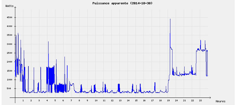
This cleaned up signal is then connected to serial to USB chip and a PHP script scrapes the data every minute. The data received from the meter is stored in a data base along with a few other bits of information: if the meter is being charged peak or off-peak rates, and the price per kWh. All this is saved on an IDE hard drive (more reliable than the SD card, surprisingly), and a ‘electricity cost per day’ is plotted on a nifty graph and served up by the Raspberry Pi.


Nicely done, and well documented.
Unfortunately not everyone have these meters. I should used a diode/photo resistor to read my electro-mecanical induction watt-hour meter :D
it’s 1200 bps, 7 bits per character, parity, with one stop bit. It’s also a 50 kHz AC signal for a binary ‘0’ and nothing for a binary ‘1’.
But… why? Who on earth designs these ridiculous schemes? Would it not have been simpler to whack a uC with a normal serial output in there than design some strange fancy type of communication?
The 50 kHz AC would allow them to run the entire circuit at mains voltage, and then use a small signal transformer for isolation. To create a DC output would require an additional isolated power supply.
But what about an optocoupler?
An optocoupler would be possible, but that would leave you with an open collector output, not a DC voltage.
I meant that amusing isolation was necessary, an optocoupler seems like an easier way to send a binary signal than a transformer. Then again, could this be a simple enough measure to make it non trivial to read?
I’m sure that isolation is necessary, one way or the other. So, that would leave you with a choice of (open collector) optocoupler or transformer. The difference is price is probably minimal. The transformer would be more robust, and would possibly also allow the measurement device to be powered by it.
If obfuscation was the goal, it would be easier to encrypt the data.
“The transformer would be more robust, and would possibly also allow the measurement device to be powered by it.” My thought exactly, but….. thius should be from an era with a rather simple reader, which I am not sure what extra it brings. I can only assume a modern day external reader has some sort of current sensor, large LCD screen and may even upload the data somewhere. This would require more power than what a simple signal transformer can do.
Agreed. A normal reader would have a screen, and probably some batteries. But I could imagine a tiny datalogger be attached to the output, and left there for a long time. In that case, it would be nice if it could snoop some power.
In France we love to say “Why do something simple, when it can be complicated” :)
It also works for Jelora, who said that there is no serial port on the rPi so he used a FTDI to convert it to serial…Wrong :p
Also, as I can see, the power supply for the pi is made of a transformer, a diode bridge and some capacitor. Would have been simpler to just use a 230V to USB power supply. And would have probably been cheaper. But as you said, we like to do it the complicated way in France ^^
Nice project though. I’d like to do something to track my power consumption but can’t find where is my electric cabinet in my apartment (why can’t I have access to it ? What happens if I break the mains by doing some crazy trials ?)
You could attach a current clamp to incoming mains wire. Wouldn’t be so accurate because it only measures current, not power, but it would give you a reasonable estimate.
This is what I was thinking to do ultimately but except mains plugs, I don’t have access to anything so the solution would be to put current clamps on all the households cables plus adding some ESP8266 and power supplies. That would cost a lot.
I’m sure you can access it if you find it.
So go try once more. Maybe they installed it under a plate in the floor like with water meters.
As a neighbor who probably has the same layout.
For clarity, that was ‘ask a neighbor’. Seems important to not get confusion there.
After having washed my floor a lot of times, there doesn’t seems to have a plate. But I will keep searching when I will be back home. I have a little room separated from apartment where I can put all cumbersome stuffs like vacuum cleaner and such. I guess this is the place I should search for. Thank you for the suggestion.
Isn’t the Raspi all 3.3v? And serial is often 5 to 12, the standard even allowing higher.
Looks like his interface connects to the RPi via the USB port not the GPIOs from the schematic from the linked page.
Could have used a logic level convertor. As we can see in the article, the output is 5V. By using the 5V supply for the raspberry and the 3.3V from the raspberry, a logic level convertor could have been easily used.
Or use a 3.3V optocoupler.
@Artenz: yes this is exactly what I thought when going to sleep yesterday but didn’t want to power up my computer again just for that ^^
It’s for IR transmission. Connect an IR LED over the signal and receive it directly with an IR receiver. Like this: http://dzlsevilgeniuslair.blogspot.dk/2013/05/quick-and-dirty-infrared-link.html
You know with all those wireless meters they seem to have in a lot of places what someone should build is a shielding box for the transmitter that only opens during business hours. Or some other way to temporarily disable the transmitter at times it needs no poling. Servo and a teensy/raspi and you got a project.
Better some protection than none
It’s probably illegal to put a shielded box around your meter, and it would be very conspicuous. You could try some rf jamming but that would probably get you in trouble as well, apparently some government agency has monitoring equipment running around.
Meters are from power companies not from the government.
And you cannot be legally required to supply the data in the middle of the night or during holidays or something, even if their user agreement requires availability.
And RF reading is never perfect anyway so they have backup systems for when it fails, thati s to say the old visual reading.
I think any modifications to the operation of the power meter is considered as illegal. If you are blocking RF transmission you could as well try to send fake data. Kind of like modifying the counter.
I’m working on the same thing (I live in france too and have the same power meter).
There’s a bunch of ways to do that but the easiest and most common on the internet is to use a SFH620A, which is an AC optocoupler. Basically you only need the SFH620A and two resistors to use it with the raspi serial gpios.
See here (french) : http://www.neufbox4.org/wiki/index.php?title=T%C3%A9l%C3%A9information_compteur_%C3%A9lectrique
Check out http://volkszaehler.org for a complete hw/sw solution to smart metering!
Check out http://volkszaehler.org for a complete smart meter solution.