One of the bigger problems with any CNC machine or 3D printer is the issue of missed steps when moving the toolhead. If a stepper motor misses a step, the entire layer of the print – and every layer thereafter – will be off by just a tiny bit. Miss a few more steps, and that print will eventually make its way into the garbage. [Misan] has the solution to this: closed loop control of DC motors for a 3D printer.
Most printer firmwares use an open loop control system for moving their motors around. Step a few times in one direction, and you know where the nozzle of a 3D printer will be. Missed steps confound the problem, and there’s no way for the firmware to know if the nozzle is where it should be at any one time.
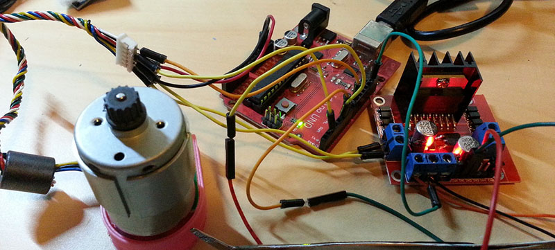
[Misan]’s solution to this was a DC motor coupled to an optical encoder. Both the motor and the encoder are connected to an Arduino Pro Mini which receives step and direction commands from the printer controller. The controller takes care of telling the motor where to go, the Arduino takes care of making sure it gets there.
The entire build is heavily derived from ServoStrap, but [Misan] has a very cool demo of his hardware: during a print, he can force the X and Y axes to either side, and the Arduino in each motor will move the print head back to where it needs to be. You can check that out below.


Nice!
I am kind of surprised he is not loosing encoder counts just relying on the inputs of the arduino.
You can counts that way just fine if you are using 500 count / rev encoders at 3D printer speed (several revs / sec). There is no way if someone tries anything modern like a 16+ bit encoder (not that they are going to be plain A quad B, anyway). I really hope anyone counting in such a flaky way would implement an invalid quadrature counter state alarm…
If you’re worried about missing steps, can’t you use a higher torque at the risk of over-heating your steppers?
Yep, that’s the solution for most, I think. The drivers I have are annoying to adjust, though, because the trims don’t have end stops, they just freewheel around so you have to eyeball where the start and end of them are…
You could also use a linear or rotary encoder but then you need to implement a closed loop control scheme as well. It’s not terribly hard or even terribly expensive but surprisingly been largely confined to commercial machines for reasons that I don’t fully understand.
The complexity and cost of encoders and closed-loop are generally high, unless you’re doing it DIY and very bare-bones. For small machines, it’s cheaper just to use slightly larger motors with slightly higher torque. The closed-loop route doesn’t become advantageous until the motors are large indeed.
Open up some old PC mices and you will find a bunch load of simple and cheap encoders. The hardest part to find is the wheel.
Screw the wheel.
Check how cheap inkjet printers do it, most of them have DC servos with optical encoders. Sometimes the head servo uses a stationary encoder strip (that is tensioned by a spring) and the sensor moves with the head.
This would be cheap and easy to DIY, you can easily print onto transparencies with a laser printer and slicing strips is also easy (unlike trying to cut out wheels and then attempting to mount them somehow), they wouldn’t even have to be very precisely cut :D
Minimal modifications to the machine, basically an add-on, with endstops even the calibration could be easily made automatic…
Generally manufacturer of precision CNC machines are using 2 encoders on each axis one inbuilt with motor i,e. rotary encoder which gives close loop feedback to system for motor only whereas a linear encoder gives the feed back for exact co-ordinates of tool head of machines, Any slip in mechanism of tool head motion is also taken in consideration.
Well most of us dont go as far as baking our steppers but they do get noisy as all get.
my Y needs more juce than the rest of the printer to handle buggers in builds that span more than 20% of the bed so i had to up the curint a bit makes for a noisy print otherwise the head may catch on a otherwise non problem bump or bugger that wouldnt effect the overall print.
But let that one bugger catch the head and skip the whole print is toast.
The code uses busy loop polling the encoder, so it will require one AVR per motor. Hope he rewrite the code to use interrupts for the encoder to drive more motors per AVR.
I’d happily use one AVR per motor if it meant I’d have more reliability than if I’d used a single AVR. AVRs are, after all pretty inexpensive.
if a busy that does nothing but polling isn’t fast enough, interrupts isn’t going to help
With AVRs it’s possible to use one of the Timer counters to count the encoder pulses in hardware. There’s usually a pin which turns into an external clock input.
The timers can read pulses up to megahertz speeds, so motors are a piece of cake.
No, it uses interrupts for the encoder signals, otherwise you risk loosing some pulses. v2 version of the code uses the interrupt on pin change to handle one of the encoder pins while the other is handled by an external interrupt. Pulse signal is handled by the other external interrupt, again to avoid losing pulses. PID loop is the main program and it can be interrupted.
Using a small FPGA would be a badass solution. There’s a lot of quadrature encoder made from FPGA out there. Also some chips used in old PC mices that was made for quadrature encoder and would output pulses and direction.
This!
This is the Right Way to make a 3D printer. DC motors for torque, with accurate feedback for positioning. It’s how robot arms work. Coupled with a Rostock design (which lends itself to this kind of actuator) it has to be the way forward.
Has anyone used the positioning strip from an inkjet printer to accurately position the printhead over a linear distance?
It’s not the same thing ?
It’s a bit different… When the encoder’s directly-connected to the motor-shaft, you don’t have to account for things like backlash of pulleys/belts, etc. This can get *really* confusing, as the motor may well try to reverse-direction if it overshoots. E.G. the motor will be physically spinning backwards, but the momentum of the system might still cause the system (and therefore encoders) to be going *forwards*… the motor would increase its torque, in the already reversed-direction, to compensate. But really all it needed to do was *stop* and wait for the momentum to slow. So, once the system has finally slowed-down on its own, the motor will have a huge reverse-torque. There’s really know way for the system to understand whether this effect is due to momentum or some sort of change-in-load (e.g. on a CNC router, the cutting-bit is dragging against material).
Also, as far as I’m aware, the positioning-strip in inkjet printers isn’t used to actually position the motor, but to determine where the motor is… It’s a heck of a lot easier/faster to toggle some print-heads at the right time than it is to move a motor to a specific position.
The positions strips are really just quadrature encoder “rolled out” to strip instead of a disc, same for stuff like digital calipers
The linear encoder strip is a lot different. It has no direction indication like a quadrature encoder so the uC has to assume the DC polarity indicates direction.
Secondly it is more to indicate motor speed rather than position. There are less encoded positions than inkjet dot positions which is fine if you are monitoring the motor speed because you can estimate position with an accuracy that is acceptable for a inkjet printer but would not be acceptable for a CNC plotter.
Thirdly the carriage goes from start to after the end of the travel distance without changing direction. If it were to stop, change speed or direction at any time during the active travel then the uC would have no hope of approximate it’s position. It’s only ‘constant speed’ that enable the uC to approximate position.
Rob – Sure as hell you didn’t see a printer in work ;-) I have an old 930C which *does* change direction of its carriage without it going to extreme position. It depends on printed area and paper size.
For the quadrature sensor to work, you could just offset the second optocoupler…
I tore down a fair amount of printers and couldn’t stand BS some people write.
@rico
I worked for an authorized warranty / service agent for Epson / HP / Canon for may years. I have probably serviced several thousand of these smaller HP inkjet printers. They don’t / can’t change direction in the print area as they need a carriage speed ‘run up’ before they can print.
Have another look at your 930C. Sure it may not go right to the end to print if the print line is short but it HAS to go past the last printed area far enough to get a speed run up for the way back.
Still not convinced? The 930C is a 600 DPI printer. To get 600 DPI from an encoder you need 600 stripes per inch. Have a look at the encoder strip – it’s not anywhere near 600 stripes per inch and therefore is not a position encoder.
As someone said earlier – the encoder is to ‘determine’ the position of the print head not to ‘control’ the position of the print head. ie the encoder provides an approximation and the software uses that to synchronize it’s timing with the print head by determining the carriage speed.
In any case most of the arguments on this page are mute. People are talking about high resolution encoders on DC motors. You would have to be an absolute genius with code to get any where near this resolution.
For motors the null points are the number of magnetic poles multiplied by the number of electromagnetic poles. In a common DC motor that is 6 – two magnetic poles and 3 electromagnetic poles. Through the fancy design of steppers you have hundreds of poles.
That means – for a common DC motor you get 6 steps per revolution or 30 degrees per step. Add to that, that you have no holding torque like you do with a stepper.
So if your thinking of putting a synchronous belt pulley in a DC motor then forget it. You need a system of gear reduction to get any reasonable accuracy. ie you can’t simply use a high res encoder and expect any decent results. Well – unless your God with code. I won’t be trying it! A DC motor has 6 zero torque positions that only momentum overcomes. How do you code for that?
“A DC motor has 6 zero torque positions that only momentum overcomes. How do you code for that?”
No it doesn’t.
DC motors experience severe cogging because of the low number of poles – that is, the torque varies a lot – but a multi-pole brushed DC motor doesn’t have any zero-torque positions because the brushes can touch more than one pair of contacts at the same time. When passing over from one pole to the next, two poles are energized at the same time.
“To get 600 DPI from an encoder you need 600 stripes per inch.”
That isn’t true either.
Take digital calipers for example. They have a rather sparse pattern of stripes clearly visible for the eye, yet they measure micrometers which are barely visible to the naked eye. The trick is that they use the pattern for absolute positioning and measure smaller differences by analog measurement between the stripes.
The calipers work capacitively, measuring how much the pattern overlaps another pattern by the capacitor they form. An optical encoder can measure the brightness of the returned light to see whether the area under the sensor is more white or more black, and thereby measure to some degree of accuracy where it is between the stripes while counting the stripes to know where it is along the entire belt.
Or you can measure the belt with a tiny camera such as a mouse sensor, and achieve any arbitrary resolution.
@Dax – “but a multi-pole brushed DC motor doesn’t have any zero-torque positions”
Well I just ordered a quadrature encoder and I will give it a go.
@Rob
DC motors still can’t drive anything directly. You need a reduction gear because they have little stall torque.
Or you need to rewind the coils for a lower top speed and more torque.
“Or you can measure the belt with a tiny camera such as a mouse sensor, and achieve any arbitrary resolution.” I’ve been curious about doing this for a while… apparently some optical/camera-based mouse-sensors actually output quadrature!
66
The linear encoder strip is a lot different. It has no direction indication like a quadrature encoder so the uC has to assume the DC polarity indicates direction.
99
Quadrature is a property of the sensor, not the strip/wheel. Think about it.
The point of connecting the encoder to the actuator instead of the motor is exactly to eliminate the backlash in the drivetrain. The feedback loop is then tuned with the slop in mind to mitigate the overshoot.
The actuator has a known momentum and spring which can be modeled and provided to the feedback path as a transfer function, so the controller can calculate where it thinks it should be as well as where it actually is. You’re essentially feeding the same controller output to the real system and a reduced virtual model of it, and subtracting the difference in outcome, which gives you the amount of loading and is used to add to the PID output to compensate for it.
It’s more complicated than standard blind PID, but nothing impossible.
Thats easier said than done. I have over a dozen servo drives running various CNC machines and every encoder is tightly coupled to the servo motor. You can connect the encoder to the end of the leadscrew or actuator but tuning the PID can be difficult or impossible if there is to much backlash or slop in the system. The motor is always always constantly adjusting itself to commanded position. If there is to much slop in the system, the motor will constantly move back and forth between encoder positions. You try to tune the PID loop so the hysterisis is minimal. To much motor jumping around can lead to the motor overheating and killing itself. (I killed a $200 Minertia motor in a similiar situation) If the tuning is under damped, it will take the motor to long to reach commanded position. If too over damped, you will overshoot the position. To much backlash makes it very hard to tune the motor. In most cases, this is why you see the encoder mounted directly on the motor shaft and try to minimize any backlash in the rest of the machine by using ballscrews or good belts/pulleys.
I don’t think anyone’s trying to say this system can’t be used for positioning of any sort… Just that *in a printer* (or similar setup) they’re most-likely not using the encoder for positioning the individual ink-jets over a specific position on the page. That would be expecting a lot of precision out of a system like this.
I’m not convinced the sort of characterization method described can overcome slop and variances in loading in the same way a motor-mounted encoder can… in an ideal-physics world, it makes sense… but in a real-world I can’t quite picture it. The friction of the carriage varies, the alignment of the linear-rod WRT the belt and other gliding-points may not be perfectly-parallel, among other things. Nevermind changes in loading due to external-forces (grit on the gliders… are you cutting a material at different depths? etc… and what if it was mounted on some sort of rotating axis, where gravity’s effects would change the direction of loading?). But I’d love to find out I’m wrong.
Some of the slop can be accounted-for similarly to *hand* machining… e.g. if your measurement needs to be precise, then you always approach the cut from the same direction.
If really high-precision is necessary, I think a combination of a motor-based encoder and an actuator-based encoder could be beneficial in order to detect/prevent oscillation…
Also combined with same-direction cuts, and a few other things, including possibly attempting to characterize *expected* slop, as described earlier.
Though, as someone else’s video-link shows, it’s ENTIRELY POSSIBLE to do low-precision (still reasonable accuracy) *POSITIONING* with an actuator-based encoder (e.g. the linear encoder in an injket)…
This is my own opinion here, but…
Don’t expect to get a lot of precision down to a few steps, and don’t expect repeatable accuracy if the load changes (especially directions)…
Most likely, don’t expect a lack of oscillation unless you account for that in the algorithm
(e.g. only power the motor in the direction you wish to go *overall*… don’t try to reverse directions to handle overshoots!)
Most likely, don’t expect to be able to accomodate varying/reversing loads
(e.g. if you physically try to move the carraige left, then right, by-hand, the motor will have to wind-up to accomodate the belt-slop in each direction…)
This is where I can imagine the characterization of the slop might be helpful in this case.. The motor *could* ramp-up then ramp-down when it thinks it should be at the right position to keep the belt tight… But without accomodating for it: even moving the carriage one tick in the other direction would cause the motor to wind-up in the other direction…
Another possible use for a system like this is if you know the loading-force will always be in a specific direction (e.g. the system’s mounted vertically and it’s never *pushing* down on something, then gravity always takes up the “slop”). (This could be useful for a 3D print-head’s Z-axis, but *not* for a CNC Mill’s router bit, if precision is necessary).
@Rob
“The linear encoder strip is a lot different. It has no direction indication like a quadrature encoder so the uC has to assume the DC polarity indicates direction.”
The linear strip certainly does provide direction, same as any other optical Quad-encoder. It’s nothing to do with the strip (or disk) they are just parallel lines on a medium. The position of the optical sensors in respect to one-another vs the width of the optical stripes gives you your 90 degree phase needed for directional info.
“Secondly it is more to indicate motor speed rather than position. There are less encoded positions than inkjet dot positions which is fine if you are monitoring the motor speed because you can estimate position with an accuracy that is acceptable for a inkjet printer but would not be acceptable for a CNC plotter.”
Agreed, there are only 300 transitions per inch. So straight quadrature decoding would give you 0.0033″ resolution. (This being 0.084mm… not too shabby for a 3D printer). If your PID loop had a handle on acceleration and velocity, you could interpolate between those transitions, as an inkjet does.
“Thirdly the carriage goes from start to after the end of the travel distance without changing direction. If it were to stop, change speed or direction at any time during the active travel then the uC would have no hope of approximate it’s position. It’s only ‘constant speed’ that enable the uC to approximate position.”
Read my answer to the first paragraph.
(FYI: If there are 300 “ticks” per inch, then the accurately-detectable resolution, using quadrature, is 300*4 = 1200 ticks per inch… as long as the quadrature-decoder implements detection of each edge of each channel)
It is the Right Way! I hope we can get 3D printers out of the dark ages of steppers. I can’t wait to get past the basic PID world so people can see what a “dumb” DC motor can do…
What do you mean by “past the basic PID world”?
Here’s a simple demo of an MSP430 decoding a printhead servo for closed loop positioning. A full solution would need to tune a PID (or PID-ish) controller. http://youtu.be/Slhp5dmajBs
As an alternative, I was considering making a “virtual stepper” that would accept step commands from EMC2 and basically step one step forward or backward per pulse from the EMC2 program. But I had other things to do and never bothered.
You can’t beat the price … Closed loop control for less than the price of a single stepper (and the controller is a micro that costs maybe $2 and a simple H-Bridge that costs about $1.50)
There are nice tricks to make cheap encoders. Frankly I have not checked Thingiverse for that but one possible way is to use a 3d printed gearbox to amplify the rotation speed of the motor shaf to get the encoder wheel to do many turns per turn of the DC motor shaft. This way you can get a nice angle resolution even with a shitty hand-made encoder.
Still, I believe reading the encoder input from the microcontroller without missing steps might be a concern. I have the feeling the atmels are already quite busy dealing with the normal motion control software, can you fit the encoder interruptions without problem?
Yeah you can do that but then you have a backlash problem. Your encoder readings will accumulate the backlash and you will end up with misprinted parts again. Oh, well.
Sooo… is it time to move from atmel MCUs to some multicore mumble jumble?
Nah, use 4000 series counter chip and then the uc can read/reset the value whenever it wants. But if you’re using a cortex chip then I’m sure it should be fast enough @ 16-80 Mhz or more, really.
Propeller is an 8 core mumble mumble that can do this cheap. Small matter of coding.
positive and negative backlash should average to 0
Yes, but if that solved the problems backlash causes, nobody would ever complain about it.
Hilariously effecitve : “let me print god damnit”
If the AVR is to slow for two motors, why not using this http://hackaday.com/2015/01/19/arm-pro-mini/ ???
32bit, 48MHz could be enough power.
Or the 96Mhz 32bit Teensy 3.1 which has plugins for the Arduino IDE, and can use most of the existing libraries…
I’ve had problems with missing encoder pulses when moving fast.
I like the Atmel Xmega series for this since:
1) They are $29
2) This one has two (or maybe three.) hardware quadrature decode peripherals.
http://store.atmel.com/PartDetail.aspx?q=p:10500183#tc:description
I also like the AVRStudio peripheral libraries. It’s click-n-compile, but you need to pay attention and make sure the clicky bits are all set right.
$29 will buy you several boards each with a Cortex M4 at +5x the speed
I do like the hardware quadrature decoders though.
Is there a cheap ARM with QDEC peripherals?
I’d go for that in a minute over AVR.
If not, how do you deal with QDEC with just GPIOs?
If you can get interrupt on both edges it helps, but even then…
How did you do it?
There are lots of inexpensive 32 bit MCU’s with multiple quadrature counters. The TI TIVA series has a low cost “Launchpad” for under $20. The Atmel ATSAM3S4 is another, but I don’t know of a low cost board for it.
Microchip makes the dsPIC line that has hardware encoder inputs. There is a pretty cheap dev board — the Microstick. The chip is ~$3 in low quantities and doesn’t require much in the way of support circuitry.
Yup, dsPIC is my suggestion too. My homemade dsPIC boards run with as few as 4x caps and 1x resistor.
I reckon ST32-Nucleo F401 can handle 4 quadrature encoders (and it cost’s $10). This is the platform I am going to use next.
The STM32 has several as far as I can tell. I’d just do it with a single fast timer interrupt and look at states rather than edges, it is more robust against noise on the transitions
NewENcoderAB contains channel A and B in its least significant bits
if(NewEncoderAB != OldEncoderAB)
{
OldEncoderAB <<= 1;
OldEncoderAB ^= NewEncoderAB;
if(OldEncoderAB & 0x2)
position–;
else
position++;
OldEncoderAB = NewEncoderAB;
}
You are not taking into account error conditions (the whole reason for using encoders).
If OldEncoderAB = 0 and NewEncoderAB=3, something has gone screwy – missed step, electrical noise, slow interrupt handler, etc. You’ll need more code in you interrupt handler to detect the fault.
It’s better to write a state machine that includes an *invalid* state transition so you need to register or flag *state valid* as well as *previous valid state* and previous direction.
So that when you get an invalid state and the next valid state is in the some direction as the previous valid state then you assume that the invalid state was the same direction.
Ooooh, I see the Arduino Due uses a SAM3x8e which has 2 eQDEC peripherals at 80 MHz!
$40 – $50, but not bad.
I’m fairly sure quite a few of the Freescale devices have Quadrature Decoders. Indeed a quick Google reminds me that the Teensy 3.1 apparently has it, and what’s more, someone is already looking into using one for motor control on their reprap: http://arduino-pi.blogspot.co.uk/2014/12/teensy-31-repstrap-printer-with-dc.html
It’s misleading since $29 is the cost of the development board, not the chip. the chips is just a few $.
you can get a board with a cortex M4 for ~$10
Be careful with these boards. Although they are handy to test the functionality of the chips, they generally don’t break out all the pins, or they already have peripherals using the pins.
Has anyone been able to open the pdf of the motor used there?
I could open it but my browser saved it to a file first.
Interesting, I have tried it both ways but it asks for a password…
This is great. I wanted to do something like this but I found some cheap steppers and went with that. I was going to use a current sense on the DC motor instead of an encoder wheel. One resistor is much cheaper.
I rotated a DC motor by hand and it has 6 positions that it favors, an average stepper has 200 so a gear reduction of 33 (approx) will get you the same resolution and much more torque.
Reduction gears introduce play so direct driving a fine pitch threaded rod would probably have suited what I wanted to do.
One 8 bit micro-controller would be more than enough using assembly and interrupts.
The next step is to have the same micro interpret the G code so that it can pause the other axises until the erroneous axis is corrected.
This has great potential because the CNC machine can self calibrate. Stepper driven CNC’s can also self calibrate but you keep having to return to a limit sensor so it would take some time to do. Perhaps I should try the same current sense on a stepper for calibration.
I think you may be mis-informed on how good a brushed DC servo motor works. My CNC currently has Minertia servo motors with 500 line encoders. With 4x quadrature that is 2000 positions per revolution. I use gecko servo drivers and can move the motor shaft to anyone of those 2000 positions with full torque. Brushed servo motors have been moving big machinery around for years with better resolution and much faster than stepper motors. Brushless DC servo motors are even better so you don’t see brushed servos motors much in industrial applications anymore.
Well I have been convinced to try this. I have ordered a cheap $4 rotary encoder and quadrature sensor from ebay.
I found that the printer encoder strips are made of polyethylene terephthalate (Mylar) which has a melting point of 260 °C so I can print linear encoders onto Mylar sheets with a laser printer and ‘fix’ the transparency issue with toner reactive foil.
Another thought I had was to combine a linear encoder with a linear driver like the voice coil driver for the laser pickup in a DVD player. Except that I will try to use Eddy currents into a non-ferric metal instead if electromagnetic currents into a ferric so as to avoid inductance issues. This sort of set up may be useful for low load applications such as low power laser.
If I have any success then I will put it up on Hackaday.io but it will take some time even before the parts get here.
One other thing, I will graph the torque / angle (0 to 360°) for the DC motor. I am expecting a sine graph at a multiple of the rotation angle.
Would anyone be interested in me posting the atmega32 code I have for operating 4 dc servo loops with potentiometer feedback?
http://ruemohr.org/~ircjunk/robots/buddy_III/p1050599.jpg
http://ruemohr.org/~ircjunk/robots/buddy_III/servo32/adc_pwm_PI_uart4/
Wow, what is it called? Did you get it working in the end?
Its a hexapod by the name of buddy III , what you see is all the legs up and over the top of its body. I need the overload boards working before I can give it full power, and I forgot to filter the current signal, currently it trips with the first pwm pulse. Look for me on youtube and I have some videos posted of some movement.
Apparently you could also use Arduino hardware timer/counter with clock source set to a pin then read & reset that before you change direction.
it would work terribly if at all, the whole point of using quadrature it’s that it will tell you when direction you are moving
You increment one counter going one way, and another counter going the other way. Both have their separate clock inputs. The difference of the two counters gives you your position. If you’re using the two 8 bit counters in an 328, you only need an interrupt every 256-512 steps to keep record of the absolute position. Once either counter rolls over, you increment the position to a global variable and both counters are zeroed.
Figuring out your position becomes slightly more complex because you have to piece it together from many variables, but you spend significantly less time in interrupts.
You need a simple gate to turn the quadrature signal to two alternating pulse trains.
still trying to wrap my head around this… how does it work with direction-changes?
There’s a logic gate that re-encodes the quadrature pulses to one pin in the micro when the rotor is turning one way, and another pin when its turning the other way. Both pins are connected to individual HW counters in the micro.
The two counter registers contain a tally of how many steps in both directions the motor has turned, so when the motor has gone three steps left and four steps right since the last measurement, and we decide left is the negative direction, the motor is now at 4 – 3 = +1 which is one step to the right from the starting point.
When you jiggle the motor one step back and forth, both counters will increase in value but the difference remains, showing the position of the shaft at the moment you read the registers.
The micro has to record the position before either of the counters overflow or else it loses track, so there has to be an interrupt when one of the counter registers reaches its top value. During this interrupt, both registers are read and zeroed, and the resulting change in position is updated in some global variable.
Other than that, no interrupts are required to read the position. The rest of the code has access to the global variable which holds the last recorded position, and you can read the counter registers for a more recent update on that.
So instead of doing an interrupt every step, you do an interrupt every couple hundred steps and that saves you a lot of instruction cycles, and makes your code run at a more consistent rate that is less dependent on your motor’s speed.
I am surprised more people aren’t using what this guy used in his Kickstarter CNC. AMS5048 magnetic encoder with some dumb cheap servos and gets great accuracy.
AMS5048A is an easy to use 360° angle position sensor (absolute encoder) with a 14-bit high resolution output and SPI interface. The maximum system accuracy is 0.05° assuming linearization and averaging is done by the external microcontroller.
I’m wondering how many output changes per second you folks are talking about on these encoders. Just a ballpark of what’s typical. I don’t have a 3D printer, and am curious why folks are missing counts, dedicating a single MCU per encoder, using hardware quadrature, etc. Maybe the obvious answer in many cases is Arduino and the associated slow hardware abstraction layers, but I’m trying to be good and refrain from automatically blaming it, especially when I don’t know what is actually required.
One issue is that when a quadrature encoder is “right on” one quadrature phase change, one of the two phase lines can oscillate back and forth at a very high rate when the device is moving at zero velocity.
It can be either phase, so using timers, interrupts etc will not work in all situations.
If your count rate is low enough, you can add lowpass filters to the phase lines to get the “real” count rate down to where your processor can handle it.
If you have a quadrature decoder guilt in hardware than can do something like 1 or 4 million counts-per-second, this filter is dead-easy to build.
If you have a processor running firmware/interrupts etc with 5 or 10 thousand counts-per-second, it gets harder.
Software will work for a lot of mechanical situations, just watch out for the ones where it’s not suitable and go with hardware QDEC. Either built-in or external IC.
Right on. The few things I’ve read about interfacing quadrature encoders all described this issue, and said the output from a encoder MUST be filtered; typically with a Schmitt trigger (which can also conveniently provide a lowpass if needed). That’s why Schmitt triggers are built into the inputs of all dedicated quadrature interfacing ICs, and the pins of an MCU that provide hardware quadrature decoding. But if you’re not using one of these, then YOU are responsible for adding them. A $0.25 74HC14 will do just fine.
I assumed this was common knowledge and practice, but if folks aren’t doing this, it’s no wonder they’re having problems with software decoding. Your comment made me wonder if my assumption was right. And sure enough, looking closer at this project,there’s no Schmitt triggers or filters, the unconditioned encoder outputs go straight into the Arduino…
Chris C. You are right about using Schmitt triggers, but it’s even MORE than that. (By the way, i had lunch with Otto H. one day. it was EXCITING!)
When the encoder is right on one “line”, one phase will go from high to low and back to high at possibly a fairly high rate. A Schmitt trigger won’t help filter that out.
A Schmitt trigger will filter out noise from a “raw” encoder, and you’ve got that nailed. Thanks.
“On the line” a phototransistor would ideally produce an analog signal, somewhere between fully high and low, that could be resolved to the last valid state via Schmitt trigger. But I suppose vibrations coupled into the encoder shaft could make it switch between fully high and low. And stepper motors create plenty of those, especially if there’s a mechanical resonance at the current step rate. Plus the phototransistors might pick up EMF and power supply noise in this environment. So you’re right, more to this than I first thought. Now I wonder if a well-chosen but simple RC filter in front of the Schmitt trigger would be sufficient, to reduce the signal the MCU has to examine to reasonably near the real maximum count rate.
Chris C: most encoders’ optical-assemblies have digital outputs… *really old* ones (like I have, from an old HP plotter) actually have discrete components (comparators, etc) to do-so. I think it has something to do with the way the photo-transistors pick up the light… it’s not exactly a sharp on/off, nor is it *fully-on* or *fully-off*. It might be handy to have that information available to a finely-tuned system, but I’m pretty sure the vast-majority of encoder pick-ups are digital-out.
You might gain something by looking at the HCTL-2000 filtering section… I’m not entirely convinced it’s the best filtration-scheme around, but its one implementation that’s used pretty commonly and I think in commercial/industrial-grade systems.
Thanks, I did take a look at the HCTL-2000 filter. Has a Schmitt-trigger input *followed* by a three step delay pipeline, with the output only changing when the signal at all three steps is equal. Looks like it functions as fully digital integrator, nearly equivalent to to *preceding* a Schmitt trigger with an RC filter. Makes sense, since transistors are a lot smaller and cheaper to fabricate in CMOS than resistors/capacitors. Plus the cutoff of the filter can be altered at will by simply changing the clock rate. Clever.
I would say that having hardware schmitt inputs would help clean up noisy encoder inputs BUT one of the first DIY servo drivers i built about 10 years ago had the encoder signals directly connected to the AVR mcu. I have three of those drivers running a small gantry CNC and is still working just fine.
These are what I built. Whatever software magic he did to make the AVR do its thing is pretty amazing. It can count over 200K encoder pulses per second. All done with hardware interrupts and good coding. I’ve spun the servo motor over 3000rpm without missing a encoder count or position. I now use gecko servo drivers on my other CNC’s but my original gantry cnc is going strong after all these years.
http://www.uhu-servo.de/servo_en/index.htm
Oops was suppose to be 150,000 encoder counts per second….
150K interrupts per seconds sounds feasible on a 10Mhz ATTiny2313, with a good ISR written in assembly, and the PID and other functions running when it can in non-interrupt context. Apparently that’s high enough to deal with any encoder noise you have. It’s faster than the response time of the phototransistors in some common optocouplers, and so might be a good target to shoot for when doing software decoding of unconditioned inputs. Though well-optimized bare metal assembly code is not something everyone knows how to, or cares to, write. What’s the max encoder PPS of your original gantry, excluding noise?
Most AVRs have schmitt-triggers on all their inputs… ;)
Chris C
Never came close to the maximum encoder counts per second that the atmel AVR can do.
Maximum speed of the gantry was 300inches/min. Leadscrew was 5threads per inch.
Servo motor had 200line encoders, at 4X quadrature, that comes out to be 800pulses per revolution.
If my math is correct the AVR only had to deal with 20,000 encoder counts per second.
if decoding is done right the oscillation is not a problem, two pins have four different states, they have to occur in order either forward or reverse, anything else can be ignored
I have thought this would be a worthwhile goal, one way of doing it is having modular motor driver/encoder counter that would be hooked up to a standard arduino mega. For example this driver accepts serial commands as well as step inputs which is huge as it allows standard reprap firmware on a mega to drive servos with high resolution quadrature encoders completely closed loop on step/direction inputs.
http://www.solutions-cubed.com/products-page/motor-controller/synaptron-micro-1/
Impressive! and i love how simple it actually works.
Based on this, im now contemplating adding optical encoders to my printer’s stepper motors, hmmmm.
I have used dedicated quadrature encoder to SPI converter chips previously.
Much easier than having the microcontroller deal with counting the pulses.
http://www.lsicsi.com/pdfs/Data_Sheets/LS7366R.pdf
Presumably what I am about to suggest has some fundamental weakness I am not aware of, but would not a simple air vane capacitor provide the necessary feedback if sufficiently strongly coupled to the DC motor drive shaft.
If used as part of a suitable R/C or L/C oscillator, it should be possible to determine relative position with fairly high accuracy.
I presume that there are drawbacks to this that I have not thought of. Air vaned capacitors are very simple and thus pretty robust, and if sealed from the harsh atmosphere and screened from RF interference might do the trick. They don’t suffer from the drawback of having a mechanical wiper, unlike the feedback pot in a typical RC servo.
Clever
Check out how digital calipers work.
Magnetic resolvers do a similar thing but more reliably than capacitance, at the cost of mechanical complexity. They’re elegant but expensive. I like the capacitor idea, you might be onto something!
If your stepper motor is losing steps an encoder cannot save you. The fact that a stepper motor has missed a step means it did not have enough torque due to axis binding, misalignment, or a collision. An encoder can only alert you after the print has already been ruined.
I can (and have) discussed the servo vs stepper tradeoff at length, but I’ll be quick. The stepper motor is never the weak link in a desktop 3d printer. It is the rigidity, repeatability, and alignment of the frame and linear motion.
If you cannot sit on your printer without it snapping in half, forget servos. If you are using v-wheels or chinese bushings on 10mm rods, forget servos. If you spent less than 500$ on linear block and rail, forget servos.
There have been several attempts at using DIY DC servos to drive 3d printers, some of which print quite well – but once you ask “What measurable performance advantage does your servo have over a stepper motor?” there are no answers. Even more so if you ask how much their setup costs in comparison to a stepper. The ultimaker 2, considered to have some of the best print quality available uses stepper motors. There are no shortcomings to stepper motors that a servo will solve in the same price range.
There are specific exceptions. In particular, due to economies of scale and some unconventional design decisions (they claim to be able to measure end-effector position in actual space, which is interesting) the m3d printer is rumored to use DC servos. Thats great, but it doesn’t mean you can buy a bunch of shitty brushed motors off ebay and expect superior performance. Many cheap brushed motors are lucky to last two weeks before burning out.
I’ve heard this argument and can’t fault your logic, but I think we disagree on a fundamental premise — I’d argue that one motion hiccup doesn’t necessarily ruin the print.
For professional parts, perhaps, but for hobbyist parts we accept little defects all over the place, and if the head has to play “catch-up” for a moment because there was a mechanical snag, the overall part is probably fine! Yes, there was a snag of some sort. No, it didn’t ruin the whole part.
A missed step is very rarely a chance occurrence. If the cause is mechanical then the axis will simply bind again every time it approaches the same location. If the stall was caused by a collision you have just dragged the hotend through the print and it cannot be recovered.
I’ve been running four stepper driven machines in varying sizes for 5 years now and the only time I have ever seen a recoverable lost step is when the g-code interpreter screws up and does not respect acceleration limits. This could sometimes happen if you had a bunch of small movements very close together such that the lookahead messed up, but I don’t think that is a problem any more.
If you really believe in encoders just slap one onto a dual-shaft stepper and you have all the robustness of a servo with the low speed performance of a stepper (not to mention low cost). Newer stepper drivers also watch the back-emf and can detect missed steps without any additional sensors.
So many topic-branches… awesome.
The “low-speed torque” issue with a DC motor is moot, using feedback. The whole point of the feedback system is to apply the necessary power to accomplish the goal. If the goal is to move one encoder-tick per second, it’ll ramp the power until it moves that tick. It may have some overshoot, but a few ticks on a 2000-count/rev is nothing. You get the same with steppers, as the shaft lags the desired/powered-position.
As someone else stated, missed-steps on a stepper are usually indicative of a recurring problem… Maybe 3D printing isn’t a great place for DC motors, but think about CNC-milling/routing… You decide to bite off more than the bit can chew at the configured-speed…? That’s 30 steps lost, right there, which now propagate into the entire design… and, most-likely, if you configured it too fast for that particular cut, it’s going to happen again numerous times.
A great example is one of the few direct-experiences I’ve actually had with CNC *machining*… a rotate-then-slice gear-cutter. It might’ve missed only a handful of steps in each rotation (for each tooth), It looked great after an hour of monitoring… but by the time it finished (after running overnight), the last-cut teeth were literally as thin as paper.
Now that I think about it, again, it’s plausible it wasn’t missing steps, at all… maybe it was just a calibration-error on a new machine. That same error would be a problem with a (geared) DC-servo as well… New ponderance.
Regardless, back to the biting-off-more-than-can-be-chewed router-example: there’s basically no way to detect (and more-importantly, recover-from) missed-steps with a stepper *alone*. With a DC motor, directly-attached encoder, proper noise-filtering, and a bit of coding, there *are no* missed-steps. If the motor can’t do the cut as quickly as requested, it sends a “not yet there” to the system, slowing all the other axes to assure the proper *path* is cut. Most-Likely, in that case, that motor is being driven with full-power, if it stalls completely, then “not yet there” will stay raised… if it just slows a bit, it’ll cut a little slower (and maybe a bit badly, since you’re trying to take too-deep of cuts). But, the same stepper-based system (with no feedback) *cannot* recover from this sort of issue; you can’t just give it more power to get to the next step… steps *will* be lost. Maybe the oscilatory-nature of missing-steps will cause it to jiggle its way to the next point, and eventually it will continue-on, but those steps are forever lost and propagate throughout the entire remainder of the process (unless there’s a feedback system).
Whether G-Code can handle “not yet there” signals is another question, entirely. I don’t know enough about it to say.
Ryan’s “forget servos” speech really got to me, though… “If you are using v-wheels or chinese bushings on 10mm rods, forget servos. If you spent less than 500$ on linear block and rail, forget servos. ” We’re talking about DC-servos, right?
No, I can definitely vouch for the fact that a DC motor with an encoder can overcome *really shitty* linear designs… (as long as the designs themselves don’t fall apart). I once worked with a two-parallel-rail system where the rails were slightly misaligned, when the motor was at one end it took less than 10% PWM to move at a certain-speed, but at the other end it took 100% PWM and was slowed dramatically. But, It Worked, and the (2-axis) paths remained accurate, and it didn’t require any additional fine-tuning of software, etc.
The only way, I can think of, that a stepper-based system could overcome that is to increase the overall power for *all* motions, at *both* ends of the system. Maybe one of these back-emf-reading stepper-drivers could handle that, but I’m willing to bet those are *way* out of the price-range of most hobbiests (especially those designing systems with linear-rails that aren’t parallel!).
I saw this and got really excited that I could build the DC + encoder strips I harvested from a couple larger printers into another 3D printer, then read the comments and got schooled. This is a great example of how this site can really bring out great discussion and hacking knowledge that could be tough to find elsewhere. Bravo to those of you that contributed on-topic, +1 to all of you.
Also, I wonder if low accuracy quadrature decoders could be used for larger scale printers that don’t need the accuracy? Think like that large printer that printed that backyard castle. Though I’m guessing holding forces come in to play more with something that size..
In other news, I guess I’ll be using those printer DC + linear movements for an at home claw machine instead!
Don’t give up on those encoder strips yet. If you search youtube for “inkjet printer encoder strip” there are several videos showing how to get a quadrature signal out of them, and also hack them for use in motion control. Whoever “schooled” you evidently hadn’t seen these:
http://youtu.be/0QLZCfqUeg4
http://youtu.be/t650YXt-_jQ
I brought this up on the RepRap forum a while ago and got shut down.
I don’t thing people think that DC motors are feasible cost wise for printers…
I’m mostly interested in pushing the speed of printers…
This is only another iteration of a not working concept. If he had done a literature search it would have become clear.
1. CNC mills are subtractive. it doesn’t matter if u remove material half a sec too late. But a printer needs temporal precision due to extruder hysterisis.
2. Closed loop solves some problems but introduces others. too solve, it will be more expensive on average. Not even cheap mills but only absolute top end come with servos, why not if the manufacturer could save money this way and get better results? Yeah, the whole industry is stupid but not this guy.
3. on a Properly configured printer missed steps do not occur up to speeds where other problems have become rampant.
Nice concept but no reason you girls all get your panties wet.
Of course it matters if an axis is half second late. High speed 3,4 or 5 axis machining centers require all the axis to be synchronized. If any one axis is is off by small amount you will run the risk of the tool/spindle crashing causing all sorts of $$$$ fixes. Of course most Machines will actually know if a axis is off and issue a emergency stop before something really bad happens. Well hopefully.
Personally I like using close loop servos.
Interesting… there’s a thought I hadn’t considered. So, basically, the extruder takes time to start/stop extruding, and therefore travel-plans (G-Code?) must be calculated to incorporate extruder start/stop times…?
I can’t believe no one has mentioned Machinekit + BeagleBone!
The combo would give you everything you need to do closed loop servo control for ~$50.
Just add some H bridges, and maybe a logic level converter or two..
Machinekit is a fork of the linuxcnc project, and is just as at home controlling Bridgeport’s and hexapods as it is 3D printers. Active, enthusiastic development is ongoing with a focus on making this extremely powerful piece of software more accessible to mere mortals.
BeagleBone is the Engineering degree holding big brother to the Pi.
Pasting from the website:
AM335x 1GHz ARM® Cortex-A8
512MB DDR3 RAM
4GB 8-bit eMMC on-board flash storage
3D graphics accelerator
NEON floating-point accelerator (horsepower for accurate acceleration and planning)
2x PRU 32-bit microcontrollers. (read that as… hard, real-time execution of motion control and closed loop feedback providing 69 channels of programmable io)
Fifty bucks.
Got around to actually testing the servo software this morning using a atmega328 jury rigged to a l298 hbridge board. I used a really nice minertia servo motor with 200 line encoder. It does really work pretty good. I little rough when spinning slow but that could just be the PID values. I used the preprogrammed values and did not change them. Spun 1500rpm with 20volt motor power supply. The motor would probably go a lot faster if I bothered to get my other higher voltage power supply but it was already connected to my CNC.
The little Arduino servo driver is neat and with some more functionality in the software, this really could be very useful to drive small motors closed loop.
Has anyone gotten this running? I threw one together using a spare arduino pro mini (and a bit of debug because the supplied block-level schematic is appropriate for the v1 sketch but the v2 sketch has the pwm on different pins) with a magnetic rotary encoder with quad output and the same h-bridge board. What I’m seeing is that it’ll run in either direction at full speed, pwm=255, but won’t ever go to a position and hold it. I put a snippet of code in the encoder acquisition ISR so I can tell it’s getting encoder pulses, and have reversed both the encoder polarity and the pwm polarity with the same behavior. My interest is in using it for a spindle speed controller that independently holds spindle speed when a cut gets heavy and reports back if it’s unable to hold spindle speed so the machine can slow the axes’ move speed, and I’ll use timer1 so I can get 16 bit pwm (that part I already have running) but the quadrature encoding interface is clever as anything and I’d love to get it running.
Did you reverse the DC polarity to the motor? If it’s back to front then the software will go flat out in the wrong direction.
I did: I get flat-out running with either polarity attachment to the motor (although in opposite direction.) Consequently I think it’s an encoder problem, like it’s getting an intermittent signal and is driving hard thinking the motor’s going too slow. (Or possibly I’m just requesting speeds faster than it can provide.)
http://youtu.be/VDxEXbkjAsg
Used the pin out in the v2 sketch to get this working today. If you have a scope make sure the output of the encoder is nice square waves. I didn’t change any of the code at all to make it work.
Sweet. Are you driving it with step/dir or from the serial port? You give me hope. I’ll work on it more tonight. Thanks!
Driving the step/dir inputs with a Tek freq generator. Good luck!!
Got a chance to play around with the PID values and got the servo motor to spin really smooth. Had to lower the D term a little. Most stepper drivers have mid band resonance problems that causes steppers to lose torque and misstep when spinning around 300-500rpm. This varies depending on motor, voltage and torque. A servo motor does not have this problem. It will spin smoothly from zero to max RPM. I believe that some of the issues with fast 3d printers is from mid band resonance causing lost steps. High performance steppers drivers like Geckodrives have anti-resonance but they are expensive. The low end stepper drivers used in most 3D printers do exhibit really bad resonance issues. I can tell you that a good servo driver/motor combination runs so much smoother/faster than most stepper motors can. Having used Geckodrive and Parker servo drivers, I’m plesently surprised how well this simple Arduino servo program works.
Peeps be talkin’ ’bout AVRs not being powerful enough… gotta remember that CNC’s been around for a long time… Encoders’ve been running on 8bit procs for ages, long before 16MHz, long before RISC when 16MHz was even close to 16MIPS… An AVR should be plenty for 2 axes if implemented well…
I did the same with a 4$ cypress psoc4
here is the vided:
http://m.youtube.com/watch?v=X1Z7Mklqd7U
Cool! Did you use the timer-based hardware encoder?
hi all, very great job :) i had this in mind when i have published the code, i’m happy too see someone have used it in a printer! i was making it with ptical rotary encoder: https://imageshack.com/a/iypz/1 and the code is completely portable on STM32 platform, i hope to add more help to the project, thanks again :)
Thank you for releasing your code in the first place :-)
Hi everyone! I used the Closed Loop Controller firmware by Misan on the “Mostly Printed CNC”.
Works flippin awesome :) Heres a Video if anyone is interested: https://www.youtube.com/watch?v=uphXy3URQ6g
Also I (badly) modified the PID tuning Tool so it can do Ramp Input response as well, which kinda worked… It’s not as tidy as Misans Version. But I think the Ramp response is much more interesting as you pretty much can’t see the integral action happening in the Step response. In the Ramp I could really see how upping the Integral feedback got the steady state error to the Ramp input to zero, which is ecaxtly what you want as the inputs to the Controller are mostly Ramps.
wow that does look awesome!
I have stayed away from closed loop because of the cost of high resolution rotary encoders. By the time you’re getting to the basic resolution of a stepper (200 steps / 360*) the encoder costs more than a stepper.
I didn’t really think about reduction motors.
So I have a question or two that I would like to ask and I would be grateful if you chose to answer.
In a true feedback system the feedback comes from axis. In your video it look like the encoder works from the motors primary shaft and not the output shaft from the reduction gear box. The difference is that having feedback from the final output will cancel error in all the previous stages.
So do you have feedback from the motor axel or from the reduction gearbox output shaft?
How much did the encoder cost?
I am thinking that if it is the case you have the feedback from the motor and that is acceptable then very cheep encoders can be used.
is somebody working with inkprinter high resolution dc motor positioning to build a delta printer. Using the drivers that the printer already have. in the market you can buy a printer for 50usd, then 3 for the delta is 150usd, and you have 3 power supplier with drivers that you can connect directly to your computer with usb, just you need mechanics and the nozzle to put all together.
Hi, glad to participate in the discussion.
I have hacked together a lathe with 3 dofs (x,y and z) with the possibility of doing up to 100000 increments / sec closed loop using 2 avrmega32 chips. The clue is to use one avr to only count pulses from the encoders and keep the other AVR for PID and setpoint/communications. The actual feedback loop runs at 200 Hz (nt too much, I know) and by using both FF and FB the perfromance is not too shabby. The setpoint generator understands 2nd order profiles, a queue and polynomial moves. The feedback loop uses some tricks to produce feedback on both position deviation and MA filtered speed.
The main AVR (running the control loops) requests the delta position from the slave AVR every feedback loop, where the slave AVR prioritizes the interrupts from the encoders. The encoder algorithm is pretty straitforward, on the falling edge of one quadrature input, the level of the other quadrature input determines whether the position is incremented or decremented.
The main AVR outputs per motor a direction and a PWM signal, that is being used by a H drive discretely built of a few gates and 4 mosfets (2 N and 2 P) The drawback is that without a level converter one is limited to around 20 Volt for the motors. Works for me. Also note that the motors are not being controlled by current, which would be the ideal situation.
I can compensate by using speed dependent feedforward. By tweaking the feedforward and feedback (PID and LP filter) parameters it should be possible to drive the motors by 80% feedforward and just 20 % feedback.
If anyone is interested I will post the code. It is not arduino (yet) but plane C for the AVR GCC compiler.
6 Channel 32-bit Quadrature Counter development shield by LSI/CSI:
https://lsicsi.com/#/products/Development-Kits/LS7366RSh
Very useful device!!!
That.is.awesome!