Fans of [Ben Heck] know that he has a soft spot for pinball machines and his projects that revolve around that topic tend to be pretty epic. This is a good example. At a trade show he saw an extra-wide format LCD screen which he thought would be perfect on a pinball build. He found out it’s a special module made for attaching to your car’s sun visor. The problem is that it only takes composite-in and he wanted higher quality video than that offers. The solution: reverse engineer the LCD protocol and implement it in an FPGA.
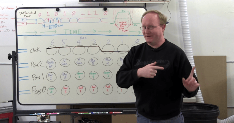
This project is a soup to nuts demonstration of replacing electronics drivers; the skill is certainly not limited to LCD modules. He starts by disassembling the hardware to find what look like differential signaling lines. With that in mind he hit the Internet looking for common video protocols which will help him figure out what he’s looking for. A four-channel oscilloscope sniffs the signal as the unit shows a blue screen with red words “NO SIGNAL”. That pattern is easy to spot since the pixels are mostly repeated except when red letters need to be displayed. Turns out the protocol is much like VGA with front porch, blanking, etc.
With copious notes about the timings [Ben] switches over to working with a Cyclone III FPGA to replace the screen’s stock controller. The product claims 800×234 resolution but when driving it using those parameters it doesn’t fill the entire screen. A bit more tweaking and he discovers the display actually has 1024×310 pixels. Bonus!
It’s going to take us a bit more study to figure out exactly how he boiled down the sniffed data to his single color-coded protocol sheet. But that’s half the fun! If you need a few more resources to understand how those signals work, check out one of our other favorite FPGA-LCD hacks.
[Thanks Sebastian]


I understand enough to say YES to your efforts. I have some pix viewers whose drive boards are trash.
It irks me to think in the post TV era how any aspect ratio goes. 1024 by 310 composite…WTF!
I can’t stand to look at distorted aspect ratio video, it’s like playing a record at the wrong speed.
Does anybody make a round screen and format?
That LCD might be useful if it is used for stereo vision – as two 512×310 displays for each eye.
Nest and the Moto360 are just some examples of round screens. They are still square pixels with a x/y coordinate system. I don’t know of any angular screens.
Unfortunately the nest screen is not round, the bezel in which is encased just covers the edges.
4D Systems make some round displays.
http://www.4dsystems.com.au/product/uLCD_220RD/
I hope he applies what he has taught himself here and makes a portable game console that uses RGB or something else instead of a pocket tv that uses composite. The snes mini/jr (the one that he used for the SNESp) outputs RGB, but it’s not wired to the A/V connector and is weak. This is an easy fix with his skills.
Or one could use the PSOne screen. It’s 5″, a 4:3 letterbox these consoles run at, and can accept RGB input. I have 2 of these screens and ran one on my RGB capable N64 for some time. N64 models 01 through 04 have the RGB lines exposed for easy tapping without needing the replacement RGB DAC conversion. I have 2 of the 04 models. Did have to use an amp on the lines though.
I personally feel the PSOne screen is the best bet for anything RGB that’s 4:3 letterbox and doesn’t need a large display. I have plans to use one of my N64 boards with one of the PSOne screens for a portable at some point. RGB driven for best video quality.
wow, I’ve never watched Ben Heck before, I’ve been missing out on a lot of info.
If you decide to start watching, prepare yourself for some of the world’s worst acting and bad attempts at humor. He provides some good info, but in a cheesy/corny way.
Right up my alley, I’m a nerd!
I have to say, I’m curious if the ribbon cable to the LCD wasn’t just carrying parallel LVTTL. If so, then it can be directly driven by a RasPi A+/B+ GPIO port, which would be pretty nifty.
While you can drive video by bit banging (the ZX80 did it years ago), it’s resource intensive and you’ll probably struggle with the timing at these resolutions (you need to push better than 333Mbits/sec to keep this screen fed). Much better to use dedicated logic (FPGAs, CPLDs or dedicated video chips).
No, it isn’t. BCM2835 has a hardware LCD driver peripheral block which is accessible over the broken out GPIO pins of the Raspberry Pi A+/B+. Just program in the timing, set the GPIO pins all to the parallel video driver peripheral and away you go. It’s the same peripheral used to get VGA out of the A+/B+ models.
is it supported in software? or behind ze BLOB?
See http://www.raspberrypi.org/gert-vga-adapter/ for details. It’s supported basically the same way HDMI or composite is, just need to set which peripheral each (and every) GPIO pin is using.
This is actually industry standard 6-bit LVDS (I think JEIDA timings), can be driven with an applications processor, RIoTboard etc.
The new (at time of writing) episode is about making a new version of his RasPi MAME handheld, but it includes an update on this project that shows it displaying large “pixels” that look like simulated LEDs. This is because A) the FPGA he used doesn’t have enough RAM for full resolution, and B) he’s using it for a pinball DMD, so he doesn’t really need/want the full resolution.
sadly it appears Ben recorced (or bought that screen) full TWO years ago
XO Vision GXS1223 is nowhere to be found now
old russian carpc forum with more technical info
http://pccar.ru/showthread.php?t=19407
there is a lot of displays with this weird aspect ratio, probably mostly used in cars as instruments display