The BeagleBoneBlack is a SoC of choice for many hackers – and quite rightly so – given its powerful features. [abhishek] is majoring in E&E from IIT-Kharagpur, India and in 2014 applied for a project at beagleboard.org via the Google Summer of Code project (GSoC). His project, BeagleLogic aims to realize a logic analyzer using the Programmable Real-Time units on board the AM335X SoC family that powers the BeagleBone and the BeagleBone Black.
The project helps create bindings of the PRU with sigrok, and also provides a web-based front-end so that the logic analyzer can be accessed in much the same way as one would use the Cloud9 IDE on the BeagleBone/BeagleBone Black to create a new application with BoneScript.
Besides it’s obvious use as a debugging tool, the logic analyzer can also be a learning tool that can be used to understand digital signals. BeagleLogic turns the BeagleBone Black into a 14-channel, 100Msps Logic Analyzer. Once loaded, it presents itself as a character device node /dev/beaglelogic. In stand-alone mode, it can do binary captures without any special client software. And when used in conjunction with the sigrok library, BeagleLogic supports software triggers and decoding for over 30 different digital protocols.
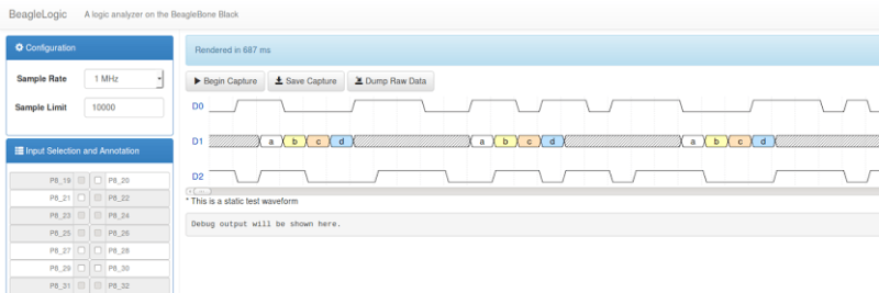
The analyzer can sample signals from 10Hz upto 100MHz, in 8 or 16 bits and up to a maximum of 14 channels. Sample depth depends on free RAM, and upto 320MB can be reserved for BeagleLogic. There’s also a web interface, which, once installed on the BeagleBone, can be accessed from port 4000 and can be used for low-volume captures (up to 3K samples).
[abhishek] recently added the BeagleLogic Cape which can be used to debug logic circuits up to 5V safely. Source files for BeagleLogic as well as the Cape are available via his github repos. [abhishek] blogged about his project on his website where there’s a lot more information and links to be found. Catch a video of BeagleLogic after the break.


That’s absolutely brilliant. Great work [abhishek]. With a bit of modification for longer sampling lengths that web interface could easily replace my old saleae logic.
Would it be possible to add a bus master feature, pretty much a signal generator with the same modules?
The firmware on the PRUs works like this: PRU1 samples at periodic intervals set by a prescaler and PRU0 writes data directly into the DDR RAM on the BeagleBone. If this is reversed i.e. PRU0 reads data from the RAM and PRU1 clocks it out at set intervals, it is theoretically possible. However there could be read latencies on the SoC interconnect bus, and further investigation would be needed to see if it works in practice.
By the way, my first cape protoypes had its inputs unintentionally (due to miswiring the DIR pin on the 74×16245 turned to outputs, so the 245 was translating from the BeagleBone pins to the pins intended as “logic input” :P and I had to fix it with magnet wire. This has since been fixed in the upstream design files.
Wonder if the same could be done using analog samples, basically creating a scope out of the beaglebone?
And in answer to my own question, its been done: http://www.element14.com/community/community/designcenter/single-board-computers/next-gen_beaglebone/blog/2013/08/04/bbb–high-speed-data-acquisition-and-web-based-ui
Why do you need a kernel module? Can’t you do this using UIO?
I did a prototype version using UIO and libprussdrv first. The problem is that:
(i) The shared memory area between the PRU and ARM core is limited to 8 MB using the UIO driver. Anything more and the driver crashes.
(ii) The UIO driver marks the shared memory area as cache coherent hence is always sync read/written. This causes memcpy from the shared area to be _very_ slow. So I would have been limited to only 8 MB of samples and forget streaming sampling from the BeagleBone except at very slow sample rates.
By going into the kernel directly and manually managing cache coherency using dma_map, dma_unmap functions and handling IRQs from the PRU within the kernel, I am able to get as much memory as I need ( > 300 MB in practice) and memcpy at the rate of a little less than 200 MB/s with the PRUs running at full steam and sampling 16bits at 100 Msps (200 MB/s). Thus given sufficient bandwidth out of the BeagleBone, it is possible to stream out that 800 Mbps of raw data comfortably. I am yet to try running LZO or LZ4 on the ARM core and be able to achieve compression of that raw data in real time.
Trust me, it was worth it.
Instead if reinventing the wheel, please the UIO driver.
Did you ask on the UIO/Kernel mailinglist? I bet not.
At that point of time, the BeagleBoard.org community members suggested moving to a remoteproc/rpmsg based framework for the PRUs which was new and was intended to replace the UIO drivers for the PRU in the upcoming times.
The BeagleLogic kernel driver builds on top of that instead.
You can also use rproc in the UIO stub. It is very sad that such a nice idea has a non-mergable hacked up kernel driver.
Why so negative? It’s a nice thing even if it doesn’t meet your design/usage ideas.
While, I really like the idea I think it would be much better for everyone if the driver would be in a shape such that we could merge it into the mainline kernel. Such that everyone can benefit from it.
I UIO does not fully address all needs, let’s talk to UIO folks and fix UIO instead of reinventing the wheel.
Know any examples of how to use UIO for allocating and accessing DMA buffers? I’m on a Zynq not a BBB but I’ll assume the driver works the same
IIRC you cannot share DMA buffers to userspace using UIO due to security concerns
Again, ask on LKML, Cc UIO folks. These are nice guys. :-)
if UIO can’t create a DMA buffer and both hand a physical address to a DMA device and expose the same to
userspace, how can it be used for anything with DMA?
Depends on the use case. If you want to give userspace full control over a DMA buffer you can also use VFIO. But in that case you’ll need an IOMMU. Again due to security concerns.
If you search the archives you’ll find patches which add DMA support to UIO.
I bought a DS logic instead for $99. Comes in a spiffy metal case and is ready to go out of the box.
http://www.seeedstudio.com/depot/DSLogic-p-2184.html
Did you try a gigabit ethernet adapter on the usb 2.0 port. I’ve seen iperf get 250Mbps half duplex between a small arm board (don’t remember if it was BBB) and a desktop. 25Msps?
Thanks for the heads up! My original idea was meant to use what exists on the BeagleBone hardware and for this setup to be as much plug-and-play as possible and avoid adding too much weight. However I am not very happy with the RNDIS gadget interface between the BeagleBone and the PC which is a dismal ~80 Mbps (I tested with iperf -c) . I do have another USB 10/100 (the dirt cheap one) and I don’t think I’d see more improvement with that.
This idea seems to be worth trying, though if given a choice, I would prefer to improve throughput of the USB gadget driver on the BeagleBone itself over an external ethernet adapter. The Bone has two of them already.
There are a few simple ways to deal with the supply of the buffer chip, on the user side:
1. Fix at 3.3V, lower voltages are probably used for faster than 100MHz anyway.
2. Select it with a jumper
3. Power the user side from the user circuit.
4. Take the supply from the user circuit and put it through a buffer opamp. The output will track the user supply and power the used side of the buffer. The power of the opamp comes from the 5V on the beagle.
I would say no 4 is the best to use.
Amazing, thanks for this! I was considering getting a saleae logic analyzer, but it seems I have all the bits I need already!
Do you have any plans to sell the cape (either as a kit or assembled) or post your design on the dirtypcbs store (where you’ll get credit for future projects)?
Don’t get that one…. Have a look at the analog discovery from digilent. There’s better digital and also analog.
I have heard some negative things about that board, it looks nice but the USB port is flimsy and apparently prone to breakage, as well as the power supplies it has like to trip ‘overcurrent’ with nothing plugged into them. I think Dave at EEBlog had this happen to him while reviewing it.
“Don’t get this, get this!” etc, get whatever suits your needs best.
EEVBlog*
And here is the review https://www.youtube.com/watch?v=Aymumu3mYl8
I don’t know what to say about the USB cable, it looks ok to me, but my usage is different than a student class who unplugs it so many times a day. Regarding the supplies…. I have never used them because most of the things i use require more than 5V/50mA, so I cannot comment on that.
But for my usage, the thing is perfect, i even gave up on my Rigol oscilloscope 99.9523% of the time(don’t have one with digital inputs). The analog band covers me and having digital signals at the same time is great for debugging embedded stuff. The one thing i really feel is limiting is the amount of memory available.
I envy the us students who can get it for $99.
I almost went with Saleae too, but I went with the Analog Discovery because I could get the student price on the discovery, making it faster and more fully featured than Saleae’s corresponding $100 part. Even if you can’t, though, the full price discovery still looks like a good competitor for Saleae.
Very nicely done. I sincerely hope you’ll be offering the cape prebuilt as a product!
I intend to make that happen, though there is no definite timeframe on when it will be. I can only say “Stay tuned for more updates” :)
If you haven’t seen it already, beta.macrofab.net is worth checking out – they do sourcing and end-to-end fab for small runs, pretty affordably. :)
Abishek,
Outstanding work! You do IIT KGP proud!
I just acquired a Beagleboard with a view to rebuilding my Astronomical CCD camera. Simply following your project and understanding how you tame the PRU’s should help. My current design (circa late 90’s) uses PIC’s to generate accurate clocking, but I would love to be able to do it all with a single Beagleboard to buffer the CCD image in local ram.
Incidentally, I graduated from IIT KGP EE class of ’66.
Reblogged this on Beagle Blogger.
I’m skeptical. “…it is possible to stream out that 800 Mbps of raw data comfortably…” How is it possible for you to stream raw data at FOUR TIMES the PRUs’ internal clock rate, disregarding the clocks-per-instruction setback and the PRU’s own overhead? Everyone else is throttled back to about 10MHz actual PRU throughput (about 2.5MHz if not directly through a PRU).
Also… I see a slew rate of 7.4nS rise or fall at 3V3, which means that the minimum round-trip cycle time for any channel of the 74LVCH16T245 is 14.8nS. That’s a far cry from any 800Mbps sampling rate.
Why only 14 channels?