Logic Analyzers: Tapping Into Raspberry Pi Secrets

Today, I’d like to highlight a tool that brings your hacking skills to a whole new level, and does that without breaking the bank – in fact, given just how much debugging time you can save, how many fun pursuits you can unlock, and the numerous features you can add, this might be one of the cheapest tools you will get. Whether it’s debugging weird problems, optimizing your code, probing around a gadget you’re reverse-engineering, or maybe trying to understand someone’s open-source library, you are likely missing out a lot if you don’t have a logic analyzer on hand!

It’s heartbreaking to me that some hackers still don’t know the value that a logic analyzer brings. Over and over again, tactical application of a logic analyzer has helped me see an entirely different perspective on something I was hacking on, and that’s just the thing I’d like to demonstrate today.

Diving In

A logic analyzer has a number of digital inputs, and it continuously reads the state of these digital inputs, sending them to your computer or showing them on a screen – it’s like a logic-level-only oscilloscope. If you have an I2C bus with one MCU controlling a sensor, connect a logic analyzer to the clock and data pins, wire up the ground, launch the logic analyzer software on your computer, and see what’s actually happening.

For instance, have you ever noticed the ID_SC and ID_SD pins on the Raspberry Pi GPIO connector? Are you wondering what they’re for? Don’t you want to check what actually happens on these pins? Let’s do that right now! Continue reading “Logic Analyzers: Tapping Into Raspberry Pi Secrets”

Screenshot of Pulseview showing capture and decode of some digital channels

Need A Logic Analyzer? Use Your Pico!

There’s a slew of hardware hacker problems that a logic analyzer is in a perfect position to solve. Whether you’re trying to understand why an SPI LCD screen doesn’t initialize, what’s up with your I2C bus, or determine the speed of an UART connection, you’ll really want to have a logic analyzer on hand. People have been using a Pi Pico as a logic analyzer in a pinch, and now [pico-coder] has shared a sigrok driver that adds proper support for a Pico to beloved tools like Pulseview.

The specs offered are impressive. Compared to the $10 “Saleae” clone analyzers we are so used to, this thing boasts 21 digital channels with up to 120 MHz capture speed, 3 ADC channels at up to 500 KHz, and hardware-based triggers. The GitHub repository linked above stores the driver files out-of-tree, but provides build instructions together with an easily flash-able uf2 firmware. It’s likely that you’ll soon see this driver in a stock Pulseview installation, however, given the submitter-friendly attitude we’ve witnessed on the sigrok mailing list. However, if you need a logic analyzer ASAP, you should follow the caringly offered quickstart guide.

We’ve covered Pulseview being used in combination with cheap accessible analyzers before — a must-watch if you need to get yourself up to speed on the value they provide to a hobbyist. If an oscilloscope is what you need and a smartphone is what you have, perhaps you’ll enjoy the Scoppy firmware for the Pico.

We thank [mip] for sharing this with us!

Scratching That Itch

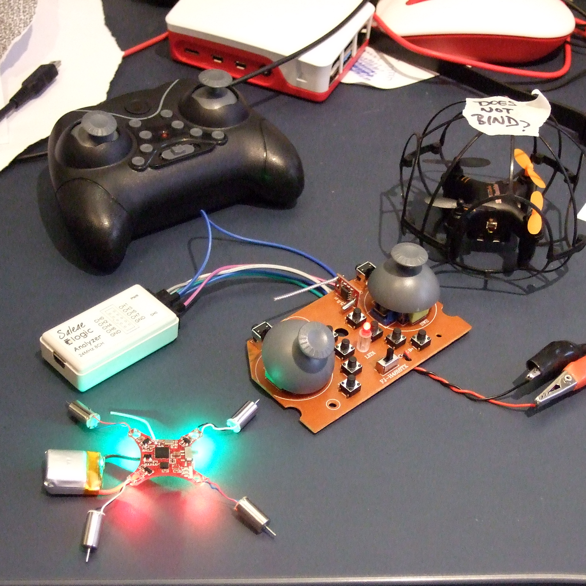
I did something silly. I bought a lot of ten “broken” cheesy indoor quadcopters on eBay — to hopefully cobble one working one together and to amuse my son. At this point, I’ve got eight working. The bad news is that they all come with dirt-cheap transmitters that aren’t really conducive to flying at all. They’d be a lot more fun if they could be controlled with a real remote. Enter the hackers.

Most all of the cheap quads are based on one of a handful of radio chipsets, although they use different protocols. An enterprising hacker could conceivably just bundle together this handful of radio modules, and the rest would be a simple matter of software. That’s exactly what Pascal Langer’s DIY Multiprotocol TX and supporting firmware does. This hobby project was so successful that compatible hardware is manufactured by more than a few Chinese companies, and non-geeks have them installed in their radios. The module lets you control virtually anything that uses 2.4 GHz. Of course, I’ve got one of them.

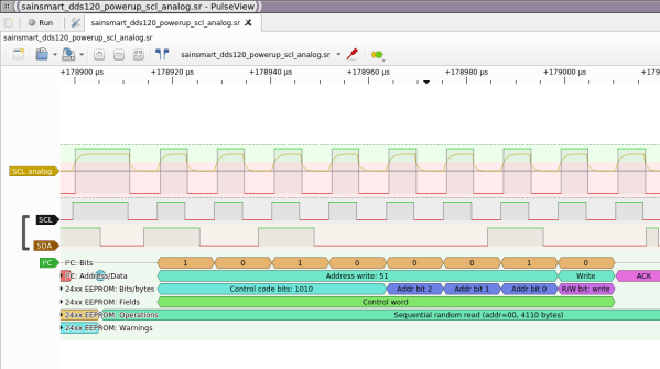
I opened up the cheesy drone’s transmitter, found that it used a popular chipset, and worked through all the different supported protocols that used it. No dice. But the radio module did have nicely labeled SPI lines, so I reached out to Pascal. A couple of Sigrok sessions later, he’d figured out that it was trying to bind on a different channel, I’d recompiled the firmware, and was playing with the drone’s other functions.

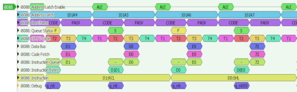
I just love a good SPI-sniffing session. sigrok-cli -d fx2lafw -c samplerate=4000000 -P spi:clk=D0:mosi=D1:cs=D2 -A spi="mosi transfer" --continuous | grep A0 | uniq reads the SPI lines, decodes the packets, filters out the commands, and removes duplicates, in real-time. All that’s left to do is wiggle the sticks, mash buttons, and take good notes.

None of this was hard, and certainly none of it was expensive. I got my drones under the control of my fancy-schmancy remote, and have a good foothold into controlling them algorithmically later on thanks to everyone’s previous work on reverse engineering these protocols. Support for DF Drone’s SkyTumbler will be included in the next DIY Multiprotocol TX release, and I spent about four or five pleasant hours on this project. Maybe only a handful of people will stumble on this particular protocol — or maybe it will just be me. I did it mostly just to scratch my own particular itch.

But that’s one way open source works, thrives, and grows. Here’s to you all out there, from the Deviation team, who did a lot of the early drone protocol reverse engineering, to Pascal for the DIY Module, to the Sigrok folks who made the tools accessible for me to piggyback on everyone’s previous work. Keep on hacking!

Easy Portable Serial Ports

Modern operating systems insulate us — as programmers, especially — from so much work. Depending on how far back you go, programmers had to manage their own fonts, their own allocation space on mass storage, or even their own memory allotments. Every year, though, it seems like things get easier and easier. So why is it so annoying to open a simple serial port? It isn’t hard, of course, but on every operating system it seems to be painful — probably in an attempt to be flexible. And it is even worse if you want portability. I needed to write some C code that read data from an FPGA’s embedded logic analyzer, and I was annoyed at having to write yet more serial port code. I have my own shim library, but it isn’t well tested and isn’t all that flexible — it does what I need, but I wanted something better. What I wound up with the serial library from Sigrok. You know Sigrok? The logic analyzer software.

 You might counter that the serial port is old hat, so no one wants to support it with modern systems. While the physical serial port might be on life support, there’s no shortage of equipment that connects via USB that appears to be a serial port. So while I was talking to an FTDI chip on an FPGA board, you could just as well be talking to an Arduino or a USB voltmeter or anything.

I guess the Sigrok developers had the same problem I did and they took the time to write a nice API and port it to major platforms. Although Sigrok uses it, they maintain it as a separate project and it was just what I needed. Sort of. I say sort of because the version installed with Ubuntu was old and I needed some features on the newest release, but — as usual — the Internet came to the rescue. A quick Git command, and four lines of build instructions and we were ready to go.

Continue reading “Easy Portable Serial Ports”

What’s Inside A Neonode Laser Sensor?

Every once in a while, you get your hands on a cool piece of hardware, and of course, it’s your first instinct to open it up and see how it works, right? Maybe see if it can be coaxed into doing just a little bit more than it says on the box? And so it was last Wednesday, when I was at the Embedded World trade fair, and stumbled on a cool touch display floating apparently in mid-air.

The display itself was a sort of focused Pepper’s Ghost illusion, reflected off of an expensive mirror made by Aska3D. I don’t know much more — I didn’t get to bring home one of the fancy glass plates — but it looked pretty good. But this display was interactive: you could touch the floating 2D projection as if it were actually there, and the software would respond. What was doing the touch response in mid-air? I’m a sucker for sensors, so I started asking questions and left with a small box of prototype Neonode zForce AIR sensor sticks to take apart.

The zForce sensors are essentially an array of IR lasers and photodiodes with some lenses that limit their field of view. The IR light hits your finger and bounces back to the photodiodes on the bar. Because the photodiodes have a limited angle over which they respond, they can be used to triangulate the distance of the finger above the display. Scanning quickly among the IR lasers and noting which photodiodes receive a reflection can locate a few fingertips in a 2D space, which explained the interactive part of the floating display. With one of these sensors, you can add a 2D touch surface to anything. It’s like an invisible laser harp that can also sense distance.

The intended purpose is fingertip detection, and that’s what the firmware is good at, but it must also be the case that it could detect the shape of arbitrary (concave) objects within its range, and that was going to be my hack. I got 90% of the way there in one night, thanks to affordable tools and free software that every hardware hacker should have in their toolbox. So read on for the unfortunate destruction of nice hardware, a tour through some useful command-line hardware-hacking tools, and gratuitous creation of animations from sniffed SPI-like data pulled off of some test points.

Continue reading “What’s Inside A Neonode Laser Sensor?”

Logic Analyzer Pushes The Limits Of Miniaturization

Careful not to sneeze while using this diminutive logic analyzer — you could send it flying across the bench.

Undertaken more for the challenge than as a practical bench tool, [Uwe Hermann]’s tiny logic analyzer is an object lesson on getting a usable circuit as small as possible. Sure, some sacrifices had to be made; it’s only an eight-channel instrument without any kind of input protection at all, and lacks niceties like an EEPROM. But that allows it to fit on a mere 11 x 11-mm fleck of PCB. That’s a pretty impressive feat of miniaturization, given that the Cypress microcontroller running the show is in QFN package that takes up 64-mm² all by itself. A micro-USB connector takes up much of the back side of the board and allows the analyzer to talk to sigrok, an open-source signal analysis suite.

Everything about the project is totally open, including the PCB files, so you can build your own if you feel up to the challenge. We’d strongly suggest you check out this primer on logic analyzers first, though, especially since it focuses on the capabilities of the sigrok suite.

Analyzing The 6502 With Python And Cheap Dev Boards

The Before Times were full of fancy logic analyzers. Connect the leads on these analyzers to a system, find that super special ROM cartridge, and you could look at the bus of a computer system in real time. We’ve come a long way since then. Now we have fast, cheap bits of hardware that can look at multiple inputs simultaneously, and there are Open Source solutions for displaying and interpreting the ones and zeros on a data bus. [hoglet] has built a very clever 6502 protocol decoder using Sigrok and a cheap 16-channel logic analyzer.

This protocol decoder is capable of looking at the ones and zeros on the data bus of a 6502-based computer. Right now, [hoglet] able to stream two million 6502 cycles directly to memory, so he’s able to capture the entire startup sequence of a BBC Micro. The hardware for this build was at first an Open Bench Logic Sniffer on a Papilio One FPGA board. This hardware was changed to an impressively inexpensive Cypress FX2 development board that was reconfigured to a 16 channel logic analyzer.

The software stack is where this really shines, and here [hoglet] documented most of the build over on the stardot forums. The basic capture is done with Sigrok, the Open Source signal analysis toolchain. This project goes a bit further than simply logging ones and zeros to a file. [hoglet] designed an entire 6502 protocol decoder with Python. Here’s something fantastic: this was [hoglet]’s first major Python project.

To capture the ones and zeros coming out of a 6502, the only connections are the eight pins on the data bus, RnW, Sync, Rdy, and Phy2. That’s only twelve pins, and no connections to the address bus, but the protocol decoder quickly starts to predict what the current program counter should be. This is a really fantastic piece of work, enabling an entire stack trace on any 6502 computer for less than $20 in parts.