There are a few all-in-one CNC/milling/plotting/3D printing/engraving bots out there that claim to be mini factories for hobbyists, prototypers, and other homebrew creators. The latest is Diyouware’s TwinTeeth, a bot obviously inspired by a few 3D printers, but something that has a few interesting features we hope will propagate through the open hardware ecosystem.
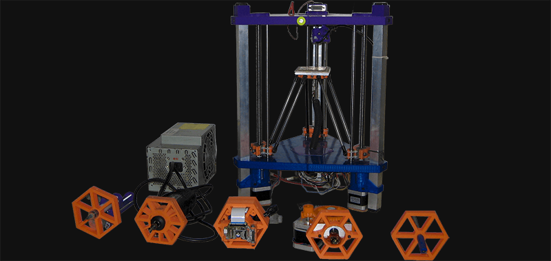
The design of the TwinTeeth is an inverse delta bot, kinematically similar to a large number of 3D printers out there. Instead of suspending the tool from a trio of arms, the TwinTeeth puts the work surface on the arms and suspends the tool from the top of the machine. There are a few neat bonuses for this setup – all the tools, from a BluRay laser diode, a Dremel, solder paste dispenser, and a plastic extruder for 3D printing can be mounted in easy to mount adapters. The TwinTooth design uses three locking pins to keep each toolhead in place, and after a little bit of software setup this machine can quickly switch between its various functions.
One very interesting feature of this bot is the ability to mask off PCBs for chemical etching with a BluRay laser diode. This actually works pretty well, as evidenced by the teams earlier work with a purpose-built PCB masker machine. The only problem with this technique is that presensitized boards must be used. If that’s an issue, no problem, just use the Dremel attachment with a v-bit cutter.


The concept is new, and I was really impressed when I saw their pre-sensitizing approach with a Blu-Ray laser.
Transparencies printed from a laser may give good results, but the toner is inherently porous and many people often double up transparencies to give better results. Having a laser to photoplot the pattern directly on the PCB will definitely give better and more repeatable results. I think the fab industry is also doing direct photoplotting right now.
Also the laser mechanism can definitely be used for making cheaper SLA 3D printers.
This technology has potential, I hope that they get their fair share for developing this thing if it goes big.
Oh joy, another unenclosed laser diode build.
Who needs retinas anyway?
Having operated several 4KW CO2 lasers, I can say from personal experience that the whole burning your retina out with consumer grade lasers issue is a bit of an overreaction from the OH&S drum-bangers.
While you do know if you get hit with a stray beam from a high power laser cutter (reflecting off shiny stainless scrap that has fallen under the bed and hitting you in the legs) the low power and scattering from even a blu-ray laser diode pointed at a surface isn’t going to burn your retinas off. The only way you will do that is if you deliberately look directly into the beam.
Pointing a 100mW blu-ray laser at a match takes about 3 seconds to ignite the match, now if you point it at the wall and look directly at the dot, the spot will be bright, might even leave a spot in your persistent vision for a few minutes but by no means will it cook your eyes. Take that same blu-ray laser and attach it to a moving head, even completely exposed and the scattering becomes a complete non-issue.
Yeah, I had this discussion with some of the people at my hackerspace when we got a laser cutter – they were worried about scattered laser light coming through some of the air holes and being seen from 20m away. Had to go through the maths with them to prove they were being stupid.
Also, if there was any real risk at 20m, then standing next to the laser cutter would set your pants on fire.
Just curious… what math were you using to say it’s safe, anyway? It’s possible you were right, but without mentioning even a loose description of how you came to that conclusion it’s far from certain.
We own laser cutters. OSHA talks in depth about exposures and classifications.
https://www.osha.gov/dts/osta/otm/otm_iii/otm_iii_6.html
Depending on the wattage, type of laser and wavelength, some lasers are more than capable of permanent and severe eye damage from even incident light. UV and IR lasers aren’t even visible, so damage can happen without you even seeing it.
Not to mention that any damage done might not be immediately apparent. you can have blind spots and not even know
The holes in question were in line with the bed, 90deg from the laser direction. That’s already a massive reduction in output intensity, as nearly all the energy that doesn’t go into the workpiece is reflected/diffused in proportion to the cosine of the angle (cos(90)=0, and cos(180)=1). So 99%+ of the energy is reflected in directions that are either solid metal or filter material. I integrated the cosine over the angle subtended by the airholes at the minimum possible distance of the laser head at the time, can’t be bothered doing it again now. But it was a negligible fraction of the total reflected energy.
Next, the energy that does actually go completely sideways and could make it out the air holes is also dispersed around the full 360 degrees of the laser axis. but since we’re only concerned about the tiny angle formed by the width of a pupil (0.5cm-ish) at 20m away, that’s another multiplier of 4×10^-5.
Uh, what? Seriously, what? A dot on the wall is the worst case? A 5-10mW red laser pointer dot on the wall is super safe to look at, yet the same even accidentally reflected off a CRT monitor into an eye can blind a person for minutes. Guess how I know. :) Now… if the 100mW dot on the WALL leaves an image in your vision… wow do I not want to catch that accidental direct eye reflection of THAT.
5-10mW is not safe to look at? Some kid I know stared down one and is fine.
CO2 Lasers are a lot safer than diodes though. The 10.4um wavelength is absorbed by pratically everything, including the surface of your eye and the fluid/lens within. It will never make it to the retina.
Visible or near visible wavelengths get focused onto the retina. Looking at the dot of a 100mW blu-ray laser is extremely uncomfortable and will leave spots in your vision whereas the dot of a 40W CO2 laser won’t even make it into your eye.
I would not want to look at the dot of a 1W 440nm diode under any circumstance.
Regarding the CO2 laser: if it doesn’t make it to your retina, where do you think the 40W goes? Probably about as much fun as grabbing a 40W soldering iron (or light bulb).
Or sticking a 40W soldering iron in your eye. Even if you don’t reach the retina, there’s plenty of excitement along the way.
Moving the bed instead of the tool saves on some things, but you’ll lose a lot of build area.
This is great. I hope these guys make enough money to keep at it. It’s not much of a stretch to adopt the toolchain to some other machine styles to maximize build area. The software they’re making is a big deal imo.
Delta robots don’t have much strength too them…why would you move your build area around??
This has magnetic quick connects and a stationary work area: http://www.zegorobotics.com/
Because moving a heavy toolhead around instead is much, much worse.
Additionally, this is a leadscrew delta, not belt driven. It seems to have more than enough strength to push a drillbit through pcb material, which is the worst case load.
We evaluated to use magnetic arms with neodymium magnets, but the Optical Pickup uses a electro-magnet to focus the laser lens so any magnetic force around it could move the lens and unfocused the laser.
The flaws you have stated are inherent to hobbyist built belt driven loose jointed deltas. I assure you that deltas can be built incredibly strong and tight. http://youtu.be/Wl5_wUVxRvw?t=37s
Is it just me or did the pcb shift noticeable sideways at (and after) each drill hit in the video at about 05:30?
I noticed that too.
At a guess, I think it’s the drill bit “skating” on the copper before the bit bites down. This can be fixed by using a different type of bit, or going over the holes with a centering drill before making the actual holes. Or maybe using a slower plunge speed.
You might also be able to compensate by pushing the board a little when the drill hits.
Still, this is a minor issue in what appears to be an awesome tool. Multiple fixtures, and I can build more of my own design? I’m sold.
Yes, you are right. We did not have a good drill bit the day we filmed the video.
The bit was 0.6mm of diameter and bigger than some pads. Also is blunt and “skate” on the cooper in some drill, as you weel say. But we were in an hurry and we did not have time to buy a good one.
In some drills it seems it loss the position but really is because it is drilling vias on GND areas, so there is not a “defined” pad on the PCB.
Thanks,
Victor.-
I fear for my eyes with that laser being unenclosed!
What first strikes me about this is that it will almost certainly do a bad job of those tasks. It’s not rigid enough for any milling. A laser diode is just way too slow for PCB exposure, plus vibration and aligning a double-side board will probably be an issue.
The exposed laser issue. Whilst it might not be that dangerous in theory, it’s easy enough to enclose so you might as well do it. I speak from the experience of having burned my hand with a 40W CO2 laser and once finding my 3 year old had climbed up onto my workbench to play with it. (It wasn’t switched on, so no damage other than sharpie marks all over it.)
Just add some clarifications. The robot is enough rigid for drilling and etching PCBs an also milling, carving and etching soft materials. It was designed mainly for UV photoengraving PCBs, drilling them and dispensing solder paste but can do other task very well. We don’t like the etching/milling process because is destructive, generates dangerous glass-fiver dust and has “mechanical” precision. We prefer laser and optical precision to print PCB.
TwinTeeth doesn’t use a laser diode. It uses a Toshiba Blu-Ray optical pickup. We hacked it in our last project and improve the electronics in this one. It’s a very low-power laser not dangerous even without a casing. I was designed to read DVD not to burn anything. And the most important think: it is focused in a short distance: a few millimetres. Laser pointers are really dangerous because has a long-range laser. This laser has a range of some millimeters as I said.
We focus the laser on the PCB using the astigmatic method and the infrared diode (to avoid blurring the film). The pickup has 3 diodes: Red, IR and UV. Once focused, we print the PCB with the UV laser.
I have been testing the robot and the laser almost a year every day and I can read this blog, even write this text, so I’m not blind!! But it does not mean we are going so stupid to turn-on the pickup and put our eyes five millimetres of the pickup lens during some minutes to see what inside.Then probably you will damage your eyes photoreceptors.
Please, read the information at our site. There we explain all these thing and also that the robot was designed to print doubled-side PC. It has a precision aluminium fixture bed and a stencil. We drill with the stencil the first 4 holes on the PCB and fix it with 4 precision pins to the fixture bed. In such a way you can align the two sides very easily: just print one side the turning around the PCB (to the right).
Thanks anyway for your comments because they let me think about if we forgot something.
Victor.-
Very cool work guys, though I too question the Use of a delta platform. By its nature a delta platform is hard to keep rigid, so milling drilling etc are not going to be very easy to keep accurate. This gets even worse with size, as the moving elements get longer and longer. You work envelope is also significantly limited with a delta configuration. It does however have benefits, some of which have been taken advantage of for fixed tools, and small desktop footprint.
That being said, this is a very good step towards finally having a tool that many hobbyists and DIY enthusiasts need in their home workshops!
Thanks very much!
Yes, delta robots are not very rigid when they face down, but in a inverted position are enough rigid for the task it was designed. You can not drill or mill steel or aluminium with TwinTeeth, but it was not designed for those tasks. It was designed for just help make us PCB prototypes at home, but also make moulds, 3D print small objects, drill or mill soft materials, etc. So it is a versatile machine which can help us to “make things” at home.
We reduced the footprint because we didn’t want to do a “professional” machine. If you see the platform size is more or less an Arduino Shield size, because is targeted to those people who make Arduino Shields at home, not big circuit boards.
We are using acme screws and anti-backslash nuts so TwinTeeth has more force and precision than any 3D printer which use timing-belts. The configuration we used with the toolhead at the top and the moving platform was though in that way to avoid vibrations. They affect to the laser beam which is very tiny with a spot of less than 0.04mm. Lasers are very sensible to resonances and vibrations. This configuration works very well because the motors are far away from the laser beam and the optical pickup is isolated from any mechanical moving device. This was the goal.
We also use an auto-leveling algorithm to maintain the platform always plain.
And at micro-level we focus the laser on the PCB to have a perfect and focused spot. Finally we use raster printing instead of vectorial printing to improve speed and quality.
Thanks,
Victor.-
I’d like to see a 3D printer head with the milling head – 3d print something, then clean it up and make it “precise” with the mill – no real load, just cleaning up surfaces, and opening up whole.
Rather than exposing pre-sensitized boards, carefully cover with packing tape to avoid bubbles then use the laser to cut around the edges of the traces. Then manually lift off the parts of tape that you wish etched away. No need for developer. Works beautifully with my 500mW violet laser at 200 mm/min