The ESP8266 is the answer to “I want something with Wifi.” Surprisingly, there are a number of engineers and hobbyists who have not heard of this chip or have heard of it but don’t really understand what it is. It’s basically the answer to everything IoT to so many engineering problems that have plagued the hobbyist and commercial world alike.
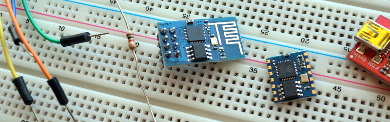
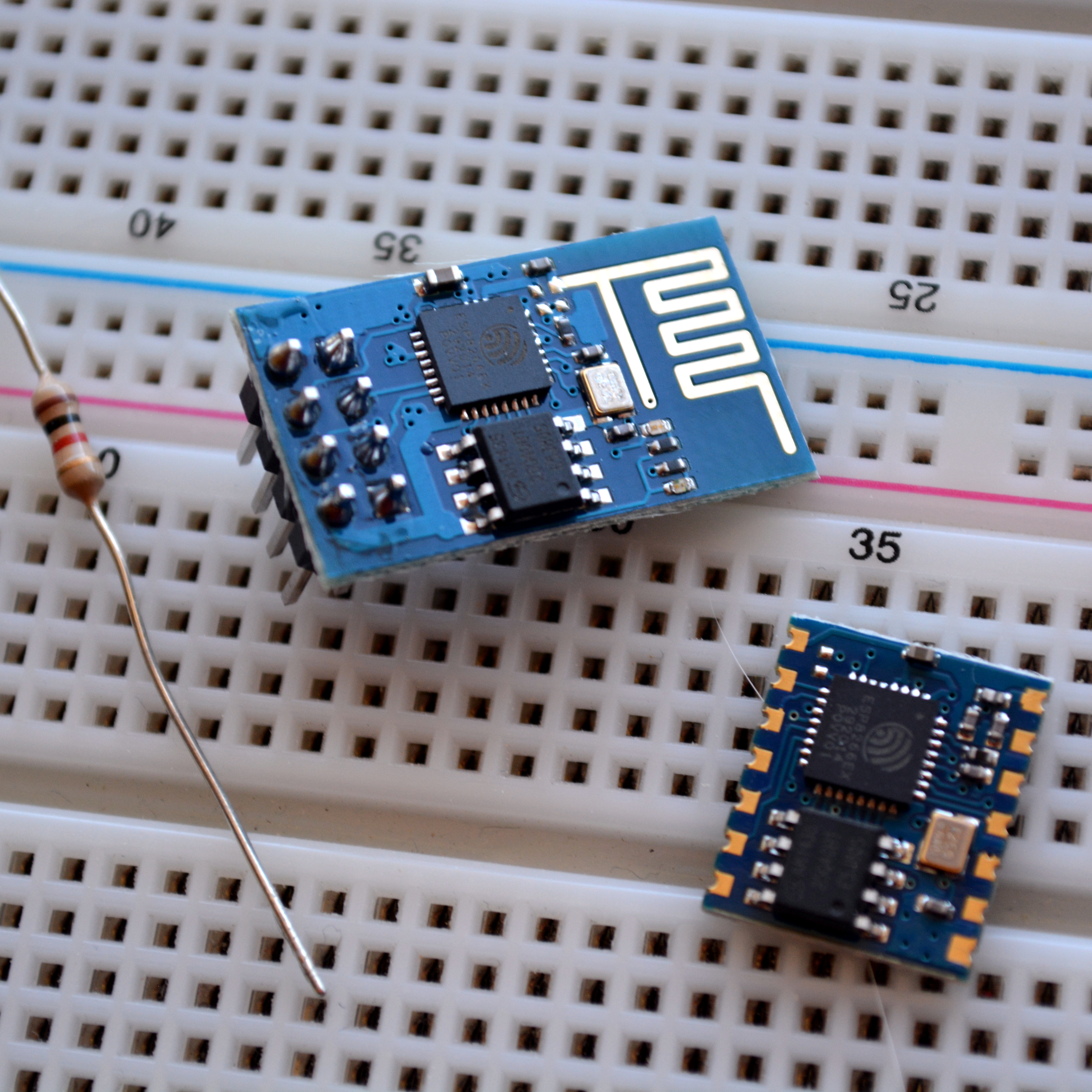
The chip is a processor with integrated RAM, some ROM, and a WiFi radio, and the only external components you will need are 4 capacitors, a crystal and an external flash! It’s CHEAP, like $4/ea cheap! Or $5 if you want it on a nice, convenient carrier board that includes all these components. The power consumption is reasonable (~200mA)1, the range is insane ~300m2 without directional equipment, and a PCB trace antenna and ~4km if you want to be ridiculous.
One place thing that more people need to know about is how to program directly for this chip. Too many times projects use it as a crutch via the AT commands. Read on and find out how to hello world with just this chip.
Know thy Hardware
First off, some background. Let’s start with a picture of it (decapped by zeptobars), and marked up by swimmmerdude.3
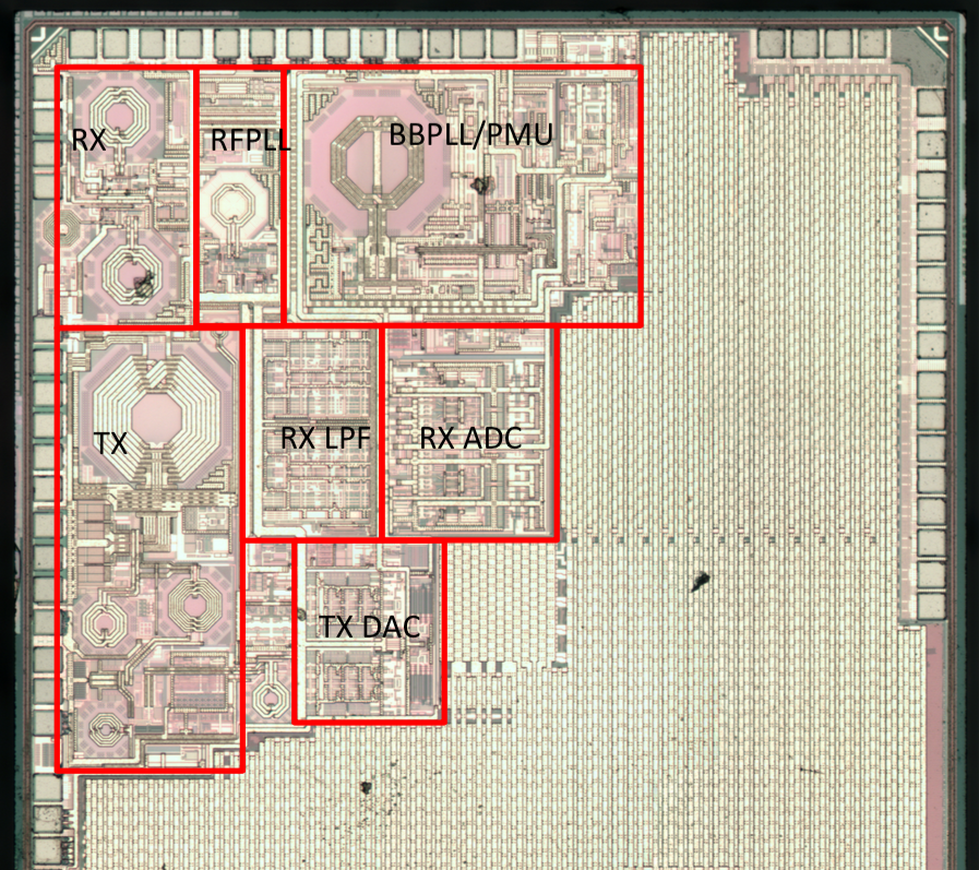
The processor by default runs at 80 MHz but can go up to 160 MHz, it has ~80kB DRAM (Data RAM), and ~35kB of high speed IRAM (Instruction RAM).4 Yes, that means it uses a Harvard architecture. The IRAM is loaded at boot with whatever the user wants to keep on-processor, though the processor can run code directly off of the external flash at a lower speed.
Firmware Background
By default when you buy these neat little boards, many of them come with the “AT” firmware, which is basically a really neat, easy, tool that lets you use these devices as simple wireless modems controlled through a serial port. That’s neat and all, but it is difficult to do particularly complicated things with this and as I mentioned before it requires the use of an external processor.
There are a few modes the chip can boot in based on the configuration of some GPIO pins. We won’t be discussing “SDCard startup” as most of the hobbyist community has not really taken to it, but we will be discussing Flash startup and UART download. Additionally, there is a remote firmware upload feature that has a few different revisions and possibilities, but we’ll save that for another post.
For the two modes we care about, the processor expects GPIO15 to low and GPIO2 to be high on boot. GPIO0 selects between the two modes we are going to discuss here. During normal operation, we would want to use a resistor to pull GPIO0 high.5 That will cause the bootloader inside the ESP8266 to read data from the EEPROM chip into the ESP8266’s IRAM and boot our program. If we set GPIO0 low, however, the boot ROM inside the ESP8266 takes over and it begins communicating over the UART. Using this boot ROM we can push our programs to the flash memory. A good way to make use of this is to connect a switch from GPIO0 to ground so you can put it into program mode at will by holding the button at power on.
This is surprisingly reliable and even supports different baud rates. I use 454,800 for my baud rate, so I can make modifications to my programs and test them very quickly. One of my projects takes less than a second to compile and about 8 seconds to burn. There are official tools to upload firmware “XTCOM”, however I personally like to use esptool.py6 because it lets you automate the flashing. Additionally, once it finishes flashing the chip, even if GPIO0 is tied low, it will cause your firmware to run. Then, if your code reboots, it will automatically re-enter the bootloader for another programming cycle. This means you can keep GPIO0 hooked to GND while you’re developing.
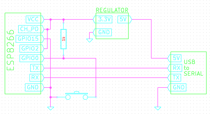
All in all, our development tools look like:
- A switch from GPIO0 to ground (with a pull-up resistor to VCC)
- GPIO2 and CH_PD connected to VCC
- GPIO15 connected to ground
- USB to TTL UART Adapter communicating with ESP8266 and providing 5V to the 3.3V regulator powering the chip
Btw… you can get USB to TTL-level UARTs super cheap, check out electrodragon for ones that are less than $1/ea!
Toolchains
Programming the ESP8266 is a little difficult to get off the ground with, but once you do, things are very easy. There are a few options for building the toolchain on Linux and OSX, plus some options in Windows. I’ve tried to keep a list of toolchains in my ws2812esp8266 readme as up-to-date as possible. Details about building the toolchain are outside of the scope of this how-to but follow that guide, or this possibly more up-to-date toolchain tutorial, and you should have no issues. Once you get a toolchain built and you can compile a firmware, like my WS2812ESP8266 firmware, you’ll be good to go for the rest of this article.
Espressif has been nice enough to distribute their SDK freely.7 This was something that absolutely shocked the community, in a good way! This was extremely generous and a move few companies make. The SDK contains an example, and headers for the ROM as well as Espressif’s library. It’s important to note that there is a community library, but every time I’ve used it so far it does not match the same level of maturity as the espressif library. Perhaps that’ll change in the future.
Be sure to check out the “include” folder in their SDK. This includes a lot of awesome functions to help get you from zero to hero in no time!
Programming: There’s a ROM for That
There’s a few things to take note of when programming the ESP8266. One is that there are a bunch of functions that are built into the ROM you can leverage. This means you don’t need to (and shouldn’t) re-implement MD5 (even with hmac), SHA1, comms with the external flash, SPI, UART functions, software floating point functions, AES, memory commands, printf, low-level IO tools, even a real-time event scheduler, and, most importantly… 802.11!
The full list of functions that reside in the on-chip ROM can be found in eagle.rom.addr.v6.ld. It would behoove you to take a look in there now and see the wonderland of awesome that’s provided out of the box.
In addition to the on-chip ROM, there’s more to their API that sits on top to make using this thing as easy as pie. We can see a number of facilitating tools. Because the ESP8266 can act as an access point or client (or both, though I’ve never tried), it has a number of tools you can use. By default the ESP8266 has it’s own unique AP. I.e. when you power it on out-of box and start their API, it starts in host-mode running its own DHCP server. You can find it by looking for a wifi network that starts with ESP8266.
Embrace Abstraction
If you’re looking to write main and have your own main loop, that’s not going to happen. While you can write main, the API expects to have its own main loop. In this sense, programming the ESP8266 is a lot like programming an Arduino.
static void ICACHE_FLASH_ATTR procTask(os_event_t *events)
{
    system_os_post(procTaskPrio, 0, 0 );
    printf( "Idle Task\n" );
}


void user_init(void)
{
    system_os_task(procTask, procTaskPrio, procTaskQueue, procTaskQueueLen);
    system_os_post(procTaskPrio, 0, 0 );
}
If you need events to happen at regular intervals, there are timer functions, os_timer_setfn, os_timer_arm that can call a function at a specific interval.
That’s great for the overall environment, however, we haven’t actually talked about how to do anything with this part. Let’s talk about how to use 802.11 with this. If you’re afraid, I don’t blame you. Trying to change 802.11 settings or connect to networks, etc is a scary proposition. Ever try doing it in Linux or Windows programatically? It’s terrifying. On the ESP8266, though, it’s easy!
Connect ESP8266 to AP in 8-lines of Code
Once your ESP8266 has booted, if something happens where it should connect to an existing network, write the following code and it’ll just happen:
const char ssid[32] = "my_home_ssid";
const char password[32] = "my_home_password";

struct station_config stationConf;

wifi_set_opmode( STATION_MODE );
os_memcpy(&stationConf.ssid, ssid, 32);
os_memcpy(&stationConf.password, password, 32);
wifi_station_set_config(&stationConf);
wifi_station_connect();
No, really, it’s just that easy. It’ll just connect to your AP, pull an IP and sit there. No fuss no muss. On top of that, it’ll remember this operation and next time you boot it, it’ll connect right up. When I’ve used it with a good AP, I was able to get it to connect, in about 2 seconds after boot. Yes, it’s really that fast.
Serving TCP
What about making a TCP server, something that can listen on a port and send back data? Surely that’s difficult. Nope. Here’s an example from an HTTP server I wrote for it:
//Allocate an "espconn"
pHTTPServer = (struct espconn *)os_zalloc(sizeof(struct espconn));
ets_memset( pHTTPServer, 0, sizeof( struct espconn ) );

//Initialize the ESPConn
espconn_create( pHTTPServer );
pHTTPServer->type = ESPCONN_TCP;
pHTTPServer->state = ESPCONN_NONE;

//Make it a TCP conention.
pHTTPServer->proto.tcp = (esp_tcp *)os_zalloc(sizeof(esp_tcp));
pHTTPServer->proto.tcp->local_port = 80;

//"httpserver_connectcb" gets called whenever you get an incoming connetion.
espconn_regist_connectcb(pHTTPServer, server_connectcb);

//Start listening!
espconn_accept(pHTTPServer);

//I don't know what default is, but I always set this.
espconn_regist_time(pHTTPServer, 15, 0);
What about receiving the connections? Here’s how you do that:
//This function gets called whenever
void ICACHE_FLASH_ATTR server_connectcb(void *arg)
{
    int i;
    struct espconn *pespconn = (struct espconn *)arg;

    //espconn's have a extra flag you can associate extra information with a connection.
    pespconn->reverse = my_http;

    //Let's register a few callbacks, for when data is received or a disconnect happens.
    espconn_regist_recvcb( pespconn, http_recvcb );
    espconn_regist_disconcb( pespconn, http_disconnetcb );
}
That’s it. Send data? espconn_sent. Close a connection? espconn_disconnect. Whenever you get data, it is passed in via the recv callback.
You’ve probably noticed I used the ICACHE_FLASH_ATTR directive, eh? Well, remember how we don’t have much IRAM? Doing this will keep the function on the flash. The instructions are cached but don’t take too long to load from the flash.
Working with GPIO
The last key point I will be covering in this article is GPIO. The pins have optional internal pull-up (GPIO0..15), and pull-down resistors (GPIO16). They can all be configured as inputs or outputs. There’s some utility functions for dealing with the GPIOs. You’ll need to call gpio_init(…) some are macros like PIN_PULLDWN_DIS(…), PIN_PULLUP_EN(…), and others found in the SDK. You can configure the input/outputs with gpio_output_set. Many of the GPIOs may have multiple functions, some of these functions are enabled by default, so, for instance, at boot you can’t do anything with GPIO12 and GPIO14 until they are selected as GPIO.
    PIN_FUNC_SELECT(PERIPHS_IO_MUX_MTDI_U, FUNC_GPIO12);
    PIN_FUNC_SELECT(PERIPHS_IO_MUX_MTMS_U, FUNC_GPIO14);
Learning to program the ESP8266 is like learning to program in any other environment. The header files provided with the SDK are very helpful when you’re trying to figure out what’s what, or to see if there’s some easy way to do what you want. So far, the data sheet hasn’t been all that helpful to me, however, Google has by far been the best tool for finding information on how to do something with this part.
The Community
Because this part really is the answer to so many problems, it has taken the hobbyist community by storm! Forums like esp8266.com and the Russian counterpart esp8266.ru are full of people trying to use the this part for awesome things! They’re full of people who have all been learning from each other about how to make the most of this little part.
Resources
[1] A general wiki for a lot of information surrounding this chip such as electrical characteristics, etc. Much of this is translated from the Chinese data sheets. https://nurdspace.nl/ESP8266
[2] Range tests I performed on the ESP8266. https://www.youtube.com/watch?v=7BYdZ_24yg0
[3] The reddit post where swimmmerdude gave his guesses at what the decapped chip looks like http://www.reddit.com/r/electronics/comments/2jq22l/esp8266_wifiserial_chip_decapped_its_actually/
[4] Memory map for address space, SPI Flash layout, registers including IOMUX: https://github.com/esp8266/esp8266-wiki/wiki/Memory-Map
[5] Discussion on the start modes of the ESP8266: http://www.esp8266.com/viewtopic.php?f=6&t=33
[6] The esptool.py site that contains information about uploading programs to the ESP8266 and alternative wiring schemes that can help with flashing. https://github.com/themadinventor/esptool/
[7] The official espressif post for the ESP SDK 0.9.5 http://bbs.espressif.com/viewtopic.php?f=5&t=154


This is great! Thanks to [cnlohr] for writing the guest post. We’ve seen a ton of people using these with AT commands and an external microcontroller but really wanted a comprehensive guide for direct programming. Well done!
I was reading “by: cnlohr” and thought “how great is that!” :) Still haven’t played with the ESPs, yet – must plan some time for it.
Omnibus 2015 candidate?
how can i connect more vibration sensor with esp8266-12. and please give me some programming instruction about esp8266-12 wifi module.
Thanks very much for this article, that’s exactly what I expect to find on HAD !
This is literally the best article I’ve ever seen written on Hackaday.
Charles as usual, hits it out of the park. Well done.
Excellent article!
Too bad my writeup wasn’t mentioned: http://www.limpkin.fr/index.php?post/2014/12/07/First-Steps-with-the-ESP8266-03-Development-Board :)
I was unaware of this at the time of writing, however, I am still not sure how I would have fit it in? Maybe just adding “And here’s some projects…”
> and, most importantly… 802.11!
802.11 is in fact in the SDK library libnet80211.a and it goes into FLASH.
That’s a decent point. Many of the higher-level functions are in flash. Not sure if it’s worth clarifying the distinction…
“Surprisingly, there are a number of engineers and hobbyists who have not heard of this chip”
For hobbyists that IS surprising. For engineers… not so much.
Engineers who design products for companies to mass produce and sell need to deal with FCC or their country’s equivalent certification. That is an expensive and difficult process. If they are already doing that they probably already have some company selling them chips that they solder directly to their PCBs, and having signed the NDAs they already have the full oficial documentation. They probably aren’t interested in hobbyist modules.
No, it doesn’t even matter if the module has already been aproved. Have they even been aproved? Again, it doesn’t really matter. Stick it in a product that you plan to produce and sell and you have to get it certified again as a whole.
RF is a finicky thing and the module could be reacting with your power bus or other components, maybe even metal parts of your case. This could cause it to radiate outside of it’s desired frequency or to focus energy in one direction thus going over legal limits for unlicensed operation in that direction.
As a hobbyist the rule is to take reasonable care within your means to ensure that you are neither broadcasting outside your limits or worse.. interfering with someone. As a professional the bar is set a whole lot higher and things are not so easy.
The double approval is a big smelly scam.
Yes and no. It’s just liability protection for OEMs so when their product gets put into another one and doesn’t work it’s not their fault. Then as mentioned there’s the odd chance that a PSU or case geometry creates conditions that violate the spectrum or EMI rules. No company wants to be the one whose product is disabling nearby pacemakers.
If that were really a huge problem, we wouldn’t have USB wifi adapters, they would all be specific to the chassis of the system they’re for.
when I was trying to buy a pcie mini card for my laptop (lenovo, sigh; they are infamous for the whitelist they use) I had to flash a hacked bios that removed the whitelist. so annoying! when you ask lenovo why they don’t let you install your own pcie wifi card, their reply is to the effect ‘we cant guarantee fcc class b’ or some crap like that. clearly its bullshit. they are trying to lock you into their own cards. strangely enough, their card IS a centrino intel card, same as what I bought at my local store. but some ID is different. the card is 100% identical, otherwise.
lenovo lies. I won’t be buying lenovo again (for several reasons). but this whitelist stuff really is so anti-consumer. HP plays the same game, too, btw.
Actually, the FCC does permit transfer of a module cert to a device using that module so long as the device adds nothing, not even a cable or new antenna, to the RF path. So it only applies to modules with either a built-in antenna, or precisely the same cable and external antenna as it was certified with as it was certified with (provided as a certified kit by the module vendor).
In the EU, full device re-certification is required, module or not. However, the top-level device cert is simplified (and much faster) if the RF module has already been certified separately. The reasoning, I believe, is the simple fact that many modules are easily misused. So modules are still the way to go in the EU for RF sub-systems that are expected to evolve quickly. The net effect in the EU is to encourage the use of custom external antennas (since you’re doing a top-level cert anyway).
Thank you very much. I plan to get some of these now!
Nice article!
The FFC part for engineers is something that I am very interested in too. Is there any commercial company that released a product with an Espressif Wi-Fi chip in it?
If there is they *certainly* won’t advertise it, it will just be discovered randomly. The last thing a legitimate company would show off is that they might be using a module that likely hasn’t been FCC certified. In fact if they did use it I’d not be the least but surprised if the liability was buried under a black blob of epoxy, and good luck finding it in the first place then.
FCC and CE certification is done at a “product” level and not at a module level. Modules do not in themselves need to be certified, only the end product they are used in.
Many wireless modules are certified at module level, it’s very common. As mentioned many times in the comments above, in some cases, it is possible to use the module certification for the entire device.
Does the Arduino D1 count?
Thanks [cnlohr] for writing such a wonder full article. Kudos!
Why 454,800 baud, and not the more standard 460800?
international exchange rate or maybe inflation?
that’s the equivalent in bitcoins, I guess (lol).
454,800 is well with tolerance for 460800. It’s probably the closest the hardware could come.
Thanks, that was a great post!
Hey cnlohr: Have you used the FreeRTOS based ‘esp_iot_rtos_sdk’?
Just ordered mine a month ago, I have started reading few docs around but this is the definitive getting started guide, bookmarked. Excellent job
Thanks for the excellent write-up! This is exactly what I needed to start getting notifications from my current ‘dumb’ appliances. I.E., when my washer and dryer are finished, what the current temp of my refrigerator/freezer is, etc.
Those are things I want to do too! But I’m too noob to pull this off based on this writeup. Will need a more basic tutorial. I guess that will seep down eventually as this grows in popularity. One thing I want to make is to every minute or so check if some LED is on or off and notify the LED state over wifi.
Check out the Lua interpreter for ESP8266. If all you’re doing is reading/writing some pins and then making some web calls, it’s a lot more Arduino-like and easier to get into. https://github.com/nodemcu/nodemcu-firmware
Agree. nodemcu is awesome and really easy to use once you got started. I’ve played with it a lot the last weeks and I’m quite impressed by how far you come with very little coding effort and how stable it is.
Be sure to check out the examples provided in the Repo to get started.
Btw I’ve used ESPlorer for all of my tests with nodemcu and even though it’s little buggy(ESPlorer) here and there it’s quite fun to play with.
I’ve had good success with NodeMCU and ESPlorer. Use esptool to flash the firmware and get to work. Look ma, no external microcontroller!
cheap, wireless and GPIO….
You had me at cheap!
That’s a good write up. I’ve been intending to play with some of these for a little while. Perhaps I’ll get to make some of those presence sensors for my home automation.
Also just as an FYI to someone in HaD, your relative path links for your citations don’t work so well from the blog frontpage.
> Also just as an FYI to someone in HaD, your relative path links for your citations don’t work so well from the blog frontpage.
yarg. That’s kinda bad. The good news is I only had to fix two links.
Most of the links in the citations don’t work either :)
:-)
Is anyone working toward an IPv6 stack on these devices?
Interesting question. Is it needed? I figured these would mostly be behind a router so IPv4 on LAN should be fine, right? Maybe I’m confused about what v6 actually does.
There do exist IPv6 LANs, with IPv6 internet connections.
For true internet of things it would be good to have all the things on IPv6, each one can have its own IP address which can (not must) be reached from the internet.
Right, that’s the idea. Plus it takes NAT entirely out of the equation if you decide to have your IoT project reach out to a server on the public Internet.
what could possibly go wrong with that idea???
@Rob
The same thing that happened before NAT became a thing every home router did; you were responsible for keeping your system safe. Industry used firewalls, so did home PCs. IoT devices that are connecting to APs in the wild should be doing some kind of confirmation of their connection before sending or receiving sensitive data. How you do that is up to you, but presuming that your AP is safe because of a password and NAT is pretty foolish; if you want data from it from externally, then it has a port open to the internet at large and that port needs to be secured whether it’s IPv4 or IPv6.
My internal network, behind a rented (i know, I know) cable modem doing NAT is still IPv4 and IPv6. Does it make a difference? Not really; it wouldn’t surprise me if the cable modem is doing NAT to IPv6 and assigning the same addresses to everybody with that variety of modem. It does ensure that when I connect out to an IPv6 site, I (should, baring strange NAT on the modem/router combo) be interacting without an IPv6-to-IPv4 pipe.
But the more of us who start to switch, and demand that the big providers switch, the better we’ll be.
If all you care about is LAN connectivity, then yes, IPv4 may be adequate for your IoT project/sensor network/et c. IPv6 makes end-to-end connectivity possible and returns routers to their proper task: deciding where packets go, not messing with the packet’s source/destination as with NAT/PAT.
Does anybody know, whats inside the ROM? It seems it can do remote firmware upgrades… and it does have an internet connection… so malware might be a problem? ;)
You have to pull a pin to update the firmware, so you need physical access.
Helpful writeup. Gives me a bit of motivation to get the toolchain setup while waiting for my 246c module taking the slow boat from China.
http://www.aliexpress.com/item/Free-Shipping-ESP8266-remote-serial-Port-WIFI-wireless-module-through-walls-Wang/32262360397.html
Agreed. A very helpful write-up. You can now download ready-built toolchains too.
For the Linux Arduino IDE – ESP8266 toolchain, there is an example (I haven’t tried this one) at “Programming ESP8266-EVB with Arduino IDE” by Olimex Ltd “https://olimex.wordpress.com/2015/03/31/programming-esp8266-evb-with-arduino-ide/”
For the equivalent Windows (64-bit only) toolchain, I downloaded and ran this one on the ESP8266 Community Forum – “This is how to install without replacing your existing IDE” at http://www.esp8266.com/viewtopic.php?f=26&t=2164
Worked first time with Arduino IDE 1.6.2.
You can also program it in Lua if you don’t need to consume too much RAM.
https://github.com/nodemcu/nodemcu-firmware
That works great for simple stuff. But thanks for this article, it is the next step for me!
This is indeed a good writeup.
I’ve been playing with this neat chip since last fall. At $5 a board, why not! The documentation is still spotty, but the wider community (such as here) have gone along way towards filling the gaps. I have had some success developing custom firmware using a Windows toolchain. Big fun!
I’ve also been working with the Spark Core and soon, the Spark Photon – they seem to be the ‘Arduinos’ of wifi-enabled controllers, and Spark has provided a lot of tools and support, so they might be a preferred starting point for those with less experience.
You may not even need the switch if you are using esptool.py. Quoting from the README:
> esptool uses the RTS and DTR modem status lines to automatically enter the bootloader. Connect RTS to CH_PD (which is used as active-low reset) and DTR to GPIO0.
Didn’t know that. Thanks for this hint!
So is there any difference between reset and ch_PD?
I just tried Reset instead of CH_PD, and it works fine.
Great guest post, we need more of these, great links.
Fantastic and informative article!!! Nicely done, HAD!
I set up a Raspberry Pi 2 with the cross compiler, eclipse, esptool etc. and hooked the serial up… Broad boarded an ESP-12 and away you go.
I was wondering whether that would work as I was reading the article. You don’t happen to have posted a writeup about this anywhere on the web? For those of us who are new to the ESP tool chain.
I would also love to hear what you did. The Pi is the only linux box in my house (hides face).
> The pins have optional internal pull-up, and pull-down resistors.
Unfortunately it is only either/or:
GPIOs 0-15 have only pullups available
GPIO16 has only pulldown available
http://www.esp8266.com/viewtopic.php?f=13&t=1613#p9687
Thank you! I would check in on HAD a lot more often if there were more articles like this one.
Why does GPIO15 need to be tied to GND?
If you don’t, the device just gets stuck in the bootloader
Excellent, thankyou. I didn’t realise how open and accessible these chips were, having only looked at them shortly after release when it was all a bit dodgy.
Don’t forget over the air updates as another option for reprogramming. The SDK comes with an example using Espressif servers but this can be easily modified to update from a local server with no special scripts.
Rob2, Hi, do you know how do i use the Over the air” upgrade? My ESP, is ESP 12 from ai-thinker, sdk 0.9.2 and i can’t send any AT commands to it…it won’t respond. It works as Access Point and i can connect with the Android IOTManager app.
Thanks!
Max
Sadly, I don’t know much anything about the normal OTA stuff… I always just rolled my own. Also, I’d always get more ESPs when in doubt. See if something unfortunate happened to it.
I’d like to use one of these in my cars Remote Starter so I can remote start the car from my phone. I want to use the default firmware with the AT commands and have an arduino mini be the brains. I’m wondering how draining is this going to be on the battery? Car may not be driven for a week.
Do these things have sleep by default?
My car had a broken switch for the light in the vanity mirror on the passenger’s visor. The light was on continuously for about three years. I only drive the car maybe once or twice a week. Even in sub zero temperatures I never had any problem starting the car after it was left alone for over a week. Does this help you to understand the capacity of a car battery?
It does!
I was doing a little research, I tested my esp8266 to draw 70mA on it’s own (can probably save a few mA removing the tiny LED) a pro mini is probably about 50mA, can probably utilize sleep and have an interrupt wake it up when there is a client present on esp8266 (will be running in AP mode).
Regarding car battery I’ve found info that it is 44Ah but that’s at 12 so for a 5v load I should deff have enough for my setup.
I also thought about adding a switch to the whole setup to only turn it on when it’s cold weather and have the whole system disengaged during the summer months.
Don’t bet on it. Most cars have a lot going on – on their own when the key is off these days. And to save money, OEMs use the lowest capacity batteries they can get away with running just the stuff they had planned for. I have a PIC and a small signal relay running off of a 7805 and if I don’t disconnect them, my battery is dead in a couple of days.
A 7805 as a permanent connected supply in a car only works if you put your device in sleep mode when not driven. This day and age I would use a POLOLU 300A or 500mA 5v or 3.3v buck converter.
200mA must be max usage and it will have(I’m guessing) several levels of power down and listening for magic wakeup packets.
This is excellent material, please produce more articles like this that revolve around delving into new platforms and systems, it’s always an interesting sort of read! cnlohr always seems to impress me one way or another, keep doing what you do man!
The best part is the lack of Italians begging for tribute for their “intellectual property”
I don’t know if I get your comment… Reference to Arduino?
I’ve just put up an ESP8266 getting-started article on my blog too: http://telecnatron.com/articles/Getting-Started-With-The-ESP8266-WIFI-Microcontroller/index.html
It covers more the getting set up side of things: wiring up the module, testing it, C SDK, NodeMCU lua environment. People who are looking to get started might find it handy when read in conjunction with the article presented here, especially those who’ve just received there first module in the mail.
thanks so much for your post, your page is very very good, i am bookmarking it for future reference, lots of good stuff
I think the only thing I would do differently is to use m4 instead of cpp, but de gustibus non est disputandem.
This is a pretty good article. If I had noticed it at the time of writing, I would have included it in a note at the end.
Five dollars? On Aliexpress you can buy ESP8266 for less than 3$!
Well you can certainly pay $3 to aliexpress for an item but whether or not you will actually get what you paid for is a different question entirely. You might get en ESP8266, you might get an iphone case, you might get a butane lighter, you might get a box of styrofoam peanuts, and what’s for certain is that you won’t get your money’s worth
I bought bunch of those modules on AE, in different versions, from different suppliers. I always received what I’ve ordered. I also bought other modules directly from China (DRA818V or DDS generators for example) without any problem.
Your suppliers from EBay are also getting their stuff from Aliexpress, You know?
Yeah but the guys on Ebay are easy to sue. And Ebay has built-in badmouthing, so when you complain about your styrofoam peanuts it actually matters to the supplier. That’s what you’re paying for, essentially. The Ebay seller does all the hassle of finding an honest Chinese electronic supplier. Or at least a consistent one.
For the sake of a couple of dollars, and possibly getting your stock sent from your own country, it’s well worth it. If you were buying 10,000 then it might be different.
Ok, now I see why there is a different perspective.
I can not imagine suing someone for not delivering few dozens of items worth few dollars each. Case would be probably dropped here in Poland anyway. So I prefer buying directly in China, than paying local supplier 2x.
You do know the chinese ebay sellers simply dump the account and make a new one if it gets a bad rep right? Also many US/EU registered sellers only have a post box in the US/EU and are operating from China. I don’t know if you can sue a post box with any results.
Whoa! I didn’t realize these things were packing so much memory.
There’s also a micropython port which I’d love to try! But it’s still in early development and does not seem to be progressing very fast at the moment.
https://github.com/micropython/micropython/tree/master/esp8266
Any idea what flavor of micropython they used for the esp8266 port?
Owl Embedded Python ?
https://www.usenix.org/conference/usenixfederatedconferencesweek/design-and-implementation-embedded-python-run-time-system
python-on-a-chip (p14p)?
https://code.google.com/p/python-on-a-chip/
Kickstarter MicroPython?
https://www.kickstarter.com/projects/214379695/micro-python-python-for-microcontrollers
The one from Kickstarter, as the name MicroPython would suggest.
Bit of shameless self-promotion here — I’ve put together an isolated dev environment for the ESP8266 using Vagrant. It makes setting up your toolchain very easy, and keeps everything in a virtual machine so as to not pollute your native environment with any extra rubbish. Check it out — https://github.com/mziwisky/esp8266-dev
There is also a development board for esp201.
http://myesp8266.blogspot.ro/2015/03/other-interesting-board-is-this-board.html
hello,
is possible to write small mesh repeater from this?
mesh network is very good but long distance is not easy. today wifi mesh is possible to run on cellphones, but trouble is range
Though I have never used it, there is a “Both” mode, where the device is configured as an AP+Station… So, maybe?
And another more detailed programming guide for ESP8266 with neat tricks in it:
https://blog.attachix.com/programming-for-esp8266-part-1/
https://blog.attachix.com/programming-for-esp8266-part-2/
I think I made a mistake in ordering the wrong esp8266. I have it connected via usb to serial and am using Termite 3.1 to terminal to it. When I send AT+RST, it echo’s the command and then says ‘ERROR’. Newer version, differnt, not sure. When I power cycle it echo’s “[Vendor:www.ai-thinker.com Version:0.9.2.4]”. Ordered from Amazon.
Can you all share what/where you are purchasing these?
Ah! Found the solution. It was a terminal issue and not appending CR-LF:
http://stackoverflow.com/a/27917455/1132773
(any of you on stackoverflow, please go upvote his response)
How do you use the functions embedded in the ROM. For example, I want to take a C string and calculate the SHA1. Are there headers somewhere that explain how to use these? How do we use the addresses when linking?
Internally, many functions are used, or self-explainatory… Sadly, for others, like MD5, you have to google and try… I’ve never tried the SHA1, but make up some headers that match how people normally do it, and that’s probably right. Hmmmm perhaps someone should start a project to make a header for the rom functions…
Yep, I figured out some of the functions and started a header file https://github.com/nodemcu/nodemcu-firmware/blob/dev/app/include/rom.h
Could I use 8051 IC to do this?
Suggest use the Tool-Stick products from silabs that are 8051 compatible, you can use ANY processor as long as it has or can be bit-banged to have a serial data stream or even a terminal session where you pretend to be a processor as a great way to teach children what a microprocessor is and why it so very powerful for all sorts of tasks
Silabs link here: http://www.silabs.com/products/mcu/Pages/ToolStick.aspx
I don’t really understand what about this would apply to the 8051? Though they can be used in conjunction, I don’t understand why you wouldn’t just make the ESP do whatever the 8051 was doing?
cnlohr asked “I don’t really understand what about this would apply to the 8051? ” in response to my post which was responding to Jack.
The 8051 is a simple inexpensive processor & the toolstick by silabs is a product that builds on the 8051 generic parts with a lot more IO options such as crossbar.
cnlohr went on to ask “I don’t understand why you wouldn’t just make the ESP do whatever the 8051 was doing?” fair question if the task was simple & you had sufficient time.
There are a couple of unclear issues using the ESP embedded processor as the wifi does require program overhead thus takes processing away from your inserted application. Overall its far quicker to not mess with any of the internal structures assuming the programmers have well documented the CPU * its s/w interface os etc within the ESP and in any case cannot necessarily warrant or even guarantee a professional process as your application has to work in conjunction with however the ESP operating system is configured. If the documentation were improved then such resistance lessens.
Engineers tend to want to avoid those unclear issues as it can also touch on IP too & also if you are already fully conversant with another processor such as 8051, 68HC11 etc then the time to market is far reduced than having to otherwise interface your application into the ESP embedded processor and in any case depends on the size of your data set which may include substantial ascii or html generation overhead. OTOH if the application is simple & not part of a commercial development process that involves any public co capital risk then sure its worth exploring but, when you have investors capital at stake then as a bridge to proof of concept its economically more viable (time & $) to interface to an existing processor & especially so if the already has stock & resident expertise etc :-)
Hi cnlohr, Thank you very much for you article. I relay appreciate your work. I have a question. All SPI,UART,GPIO and other functions are preloaded on the ROM ? then where our program gets loaded ?
Will you please explain me how the ROM and Program memory works ?
I want to connect esp8266 wifi module to arduino r3. And using this i want to transmit data to cell phone.How this can be done?
I want esp8266 to access the home wifi by entering wifi password manually not by programming cox I’m developing an app to communicate with esp8266. So plz kindly provide me some help about how can I enter wifi password thought my app.
The basics would be:
Start it in AP mode, serve a page (or listen for a socket connection) asking for wifi settings, save these to flash. Once settings are entered, change to station mode and attempt to connect. If successful, stay as a station and use saved settings in the future. If connection is not successful, delete saved settings and revert to AP mode to serve a page (or socket) asking for new credentials.
Kudos for this writeup @cnlohr! Really appreciate your efforts! Cheers.
Can someone explain how to get wifi signal strength as input in my program from esp8266 using AT+CWLAP command?
How to use the result on the serial monitor as input into my program in arduino IDE
Hi cnlohr,
I am working on Arduino and ESP8266, i want to configure esp8266 with ESP SDK API’s so what should be the procedure?
and i don’t want use AT command
Read the instructions over at esp open sdk on github.
I’d recommend getting the ones with metal shields, as these are likely through fcc. Also, does programming them other than using them as simple spi wifi modules violate the fcc certification? This is a big deal if making a commercial product.
I don’t see any drivers for the ADC in esp8266 NonOS SDK. Any thoughts?