The ESP8266 is the answer to “I want something with Wifi.” Surprisingly, there are a number of engineers and hobbyists who have not heard of this chip or have heard of it but don’t really understand what it is. It’s basically the answer to everything IoT to so many engineering problems that have plagued the hobbyist and commercial world alike.
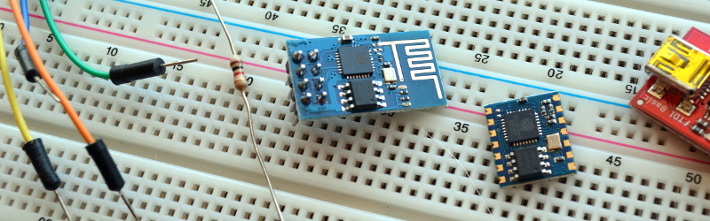
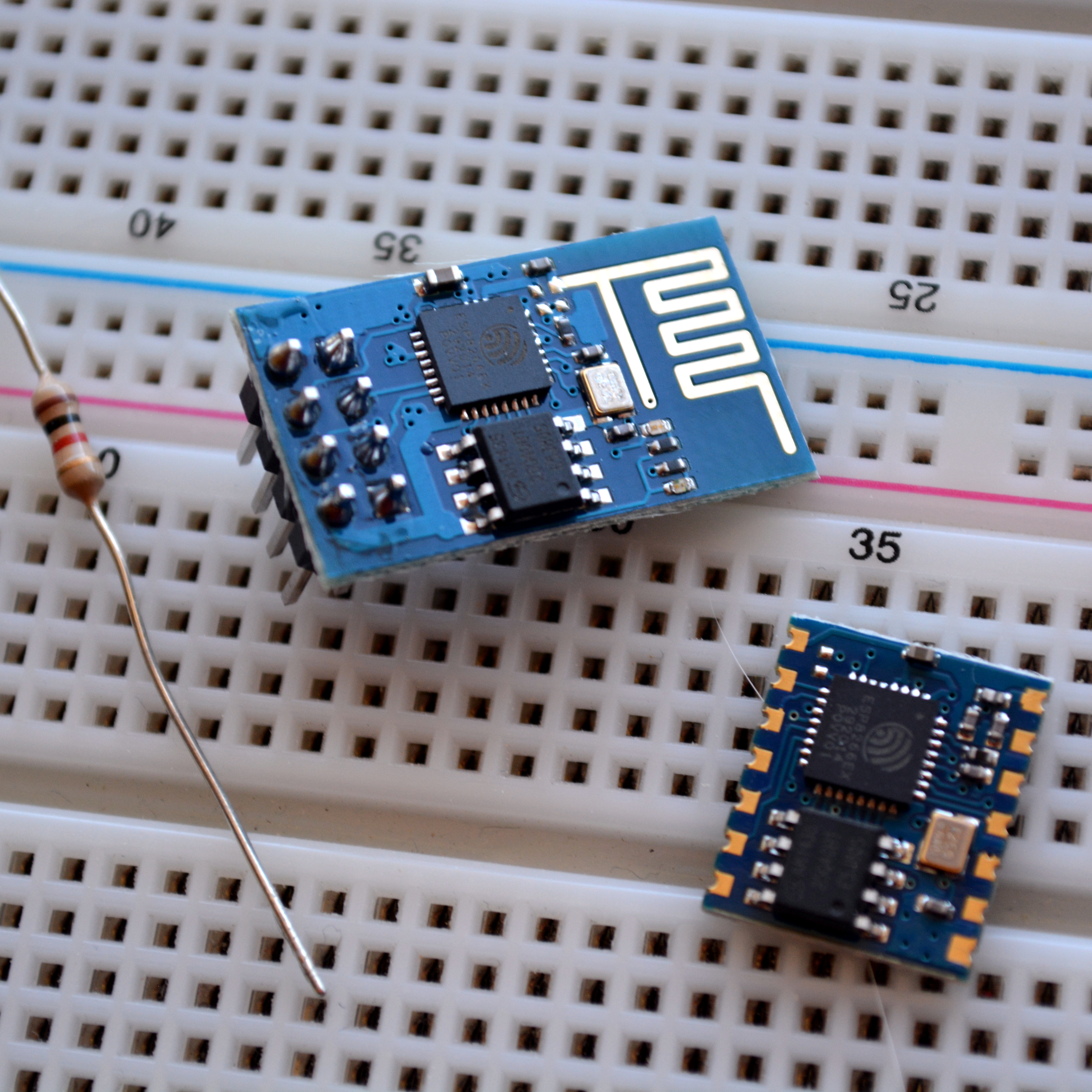
The chip is a processor with integrated RAM, some ROM, and a WiFi radio, and the only external components you will need are 4 capacitors, a crystal and an external flash! It’s CHEAP, like $4/ea cheap! Or $5 if you want it on a nice, convenient carrier board that includes all these components. The power consumption is reasonable (~200mA)1, the range is insane ~300m2 without directional equipment, and a PCB trace antenna and ~4km if you want to be ridiculous.
One place thing that more people need to know about is how to program directly for this chip. Too many times projects use it as a crutch via the AT commands. Read on and find out how to hello world with just this chip.
Know thy Hardware
First off, some background. Let’s start with a picture of it (decapped by zeptobars), and marked up by swimmmerdude.3
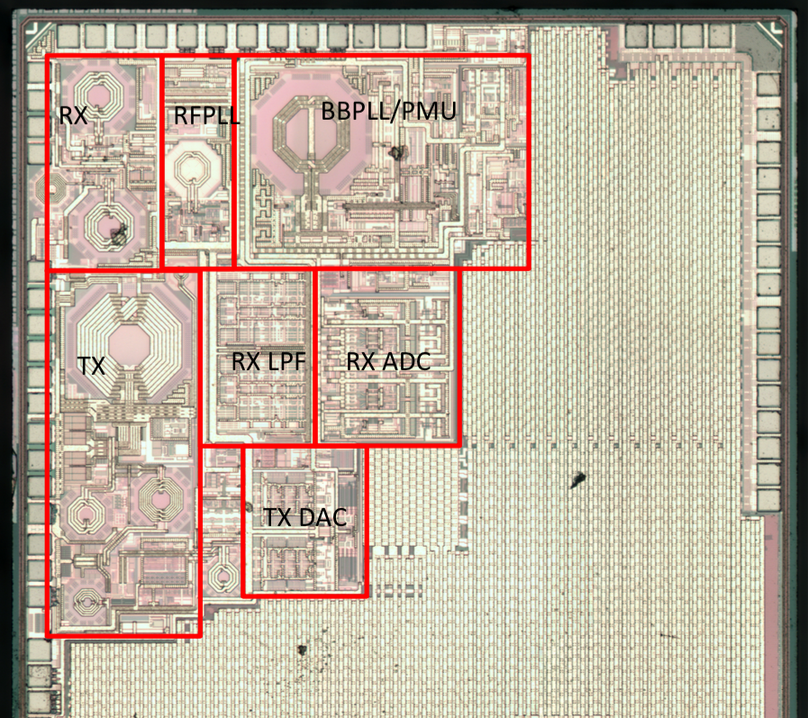
The processor by default runs at 80 MHz but can go up to 160 MHz, it has ~80kB DRAM (Data RAM), and ~35kB of high speed IRAM (Instruction RAM).4 Yes, that means it uses a Harvard architecture. The IRAM is loaded at boot with whatever the user wants to keep on-processor, though the processor can run code directly off of the external flash at a lower speed.
Firmware Background
By default when you buy these neat little boards, many of them come with the “AT” firmware, which is basically a really neat, easy, tool that lets you use these devices as simple wireless modems controlled through a serial port. That’s neat and all, but it is difficult to do particularly complicated things with this and as I mentioned before it requires the use of an external processor.
There are a few modes the chip can boot in based on the configuration of some GPIO pins. We won’t be discussing “SDCard startup” as most of the hobbyist community has not really taken to it, but we will be discussing Flash startup and UART download. Additionally, there is a remote firmware upload feature that has a few different revisions and possibilities, but we’ll save that for another post.
For the two modes we care about, the processor expects GPIO15 to low and GPIO2 to be high on boot. GPIO0 selects between the two modes we are going to discuss here. During normal operation, we would want to use a resistor to pull GPIO0 high.5 That will cause the bootloader inside the ESP8266 to read data from the EEPROM chip into the ESP8266’s IRAM and boot our program. If we set GPIO0 low, however, the boot ROM inside the ESP8266 takes over and it begins communicating over the UART. Using this boot ROM we can push our programs to the flash memory. A good way to make use of this is to connect a switch from GPIO0 to ground so you can put it into program mode at will by holding the button at power on.
This is surprisingly reliable and even supports different baud rates. I use 454,800 for my baud rate, so I can make modifications to my programs and test them very quickly. One of my projects takes less than a second to compile and about 8 seconds to burn. There are official tools to upload firmware “XTCOM”, however I personally like to use esptool.py6 because it lets you automate the flashing. Additionally, once it finishes flashing the chip, even if GPIO0 is tied low, it will cause your firmware to run. Then, if your code reboots, it will automatically re-enter the bootloader for another programming cycle. This means you can keep GPIO0 hooked to GND while you’re developing.
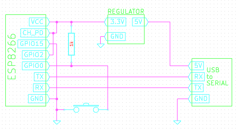
All in all, our development tools look like:
- A switch from GPIO0 to ground (with a pull-up resistor to VCC)
- GPIO2 and CH_PD connected to VCC
- GPIO15 connected to ground
- USB to TTL UART Adapter communicating with ESP8266 and providing 5V to the 3.3V regulator powering the chip
Btw… you can get USB to TTL-level UARTs super cheap, check out electrodragon for ones that are less than $1/ea!
Toolchains
Programming the ESP8266 is a little difficult to get off the ground with, but once you do, things are very easy. There are a few options for building the toolchain on Linux and OSX, plus some options in Windows. I’ve tried to keep a list of toolchains in my ws2812esp8266 readme as up-to-date as possible. Details about building the toolchain are outside of the scope of this how-to but follow that guide, or this possibly more up-to-date toolchain tutorial, and you should have no issues. Once you get a toolchain built and you can compile a firmware, like my WS2812ESP8266 firmware, you’ll be good to go for the rest of this article.
Espressif has been nice enough to distribute their SDK freely.7 This was something that absolutely shocked the community, in a good way! This was extremely generous and a move few companies make. The SDK contains an example, and headers for the ROM as well as Espressif’s library. It’s important to note that there is a community library, but every time I’ve used it so far it does not match the same level of maturity as the espressif library. Perhaps that’ll change in the future.
Be sure to check out the “include” folder in their SDK. This includes a lot of awesome functions to help get you from zero to hero in no time!
Programming: There’s a ROM for That
There’s a few things to take note of when programming the ESP8266. One is that there are a bunch of functions that are built into the ROM you can leverage. This means you don’t need to (and shouldn’t) re-implement MD5 (even with hmac), SHA1, comms with the external flash, SPI, UART functions, software floating point functions, AES, memory commands, printf, low-level IO tools, even a real-time event scheduler, and, most importantly… 802.11!
The full list of functions that reside in the on-chip ROM can be found in eagle.rom.addr.v6.ld. It would behoove you to take a look in there now and see the wonderland of awesome that’s provided out of the box.
In addition to the on-chip ROM, there’s more to their API that sits on top to make using this thing as easy as pie. We can see a number of facilitating tools. Because the ESP8266 can act as an access point or client (or both, though I’ve never tried), it has a number of tools you can use. By default the ESP8266 has it’s own unique AP. I.e. when you power it on out-of box and start their API, it starts in host-mode running its own DHCP server. You can find it by looking for a wifi network that starts with ESP8266.
Embrace Abstraction
If you’re looking to write main and have your own main loop, that’s not going to happen. While you can write main, the API expects to have its own main loop. In this sense, programming the ESP8266 is a lot like programming an Arduino.
static void ICACHE_FLASH_ATTR procTask(os_event_t *events)
{
    system_os_post(procTaskPrio, 0, 0 );
    printf( "Idle Task\n" );
}


void user_init(void)
{
    system_os_task(procTask, procTaskPrio, procTaskQueue, procTaskQueueLen);
    system_os_post(procTaskPrio, 0, 0 );
}
If you need events to happen at regular intervals, there are timer functions, os_timer_setfn, os_timer_arm that can call a function at a specific interval.
That’s great for the overall environment, however, we haven’t actually talked about how to do anything with this part. Let’s talk about how to use 802.11 with this. If you’re afraid, I don’t blame you. Trying to change 802.11 settings or connect to networks, etc is a scary proposition. Ever try doing it in Linux or Windows programatically? It’s terrifying. On the ESP8266, though, it’s easy!
Connect ESP8266 to AP in 8-lines of Code
Once your ESP8266 has booted, if something happens where it should connect to an existing network, write the following code and it’ll just happen:
const char ssid[32] = "my_home_ssid";
const char password[32] = "my_home_password";

struct station_config stationConf;

wifi_set_opmode( STATION_MODE );
os_memcpy(&stationConf.ssid, ssid, 32);
os_memcpy(&stationConf.password, password, 32);
wifi_station_set_config(&stationConf);
wifi_station_connect();
No, really, it’s just that easy. It’ll just connect to your AP, pull an IP and sit there. No fuss no muss. On top of that, it’ll remember this operation and next time you boot it, it’ll connect right up. When I’ve used it with a good AP, I was able to get it to connect, in about 2 seconds after boot. Yes, it’s really that fast.
Serving TCP
What about making a TCP server, something that can listen on a port and send back data? Surely that’s difficult. Nope. Here’s an example from an HTTP server I wrote for it:
//Allocate an "espconn"
pHTTPServer = (struct espconn *)os_zalloc(sizeof(struct espconn));
ets_memset( pHTTPServer, 0, sizeof( struct espconn ) );

//Initialize the ESPConn
espconn_create( pHTTPServer );
pHTTPServer->type = ESPCONN_TCP;
pHTTPServer->state = ESPCONN_NONE;

//Make it a TCP conention.
pHTTPServer->proto.tcp = (esp_tcp *)os_zalloc(sizeof(esp_tcp));
pHTTPServer->proto.tcp->local_port = 80;

//"httpserver_connectcb" gets called whenever you get an incoming connetion.
espconn_regist_connectcb(pHTTPServer, server_connectcb);

//Start listening!
espconn_accept(pHTTPServer);

//I don't know what default is, but I always set this.
espconn_regist_time(pHTTPServer, 15, 0);
What about receiving the connections? Here’s how you do that:
//This function gets called whenever
void ICACHE_FLASH_ATTR server_connectcb(void *arg)
{
    int i;
    struct espconn *pespconn = (struct espconn *)arg;

    //espconn's have a extra flag you can associate extra information with a connection.
    pespconn->reverse = my_http;

    //Let's register a few callbacks, for when data is received or a disconnect happens.
    espconn_regist_recvcb( pespconn, http_recvcb );
    espconn_regist_disconcb( pespconn, http_disconnetcb );
}
That’s it. Send data? espconn_sent. Close a connection? espconn_disconnect. Whenever you get data, it is passed in via the recv callback.
You’ve probably noticed I used the ICACHE_FLASH_ATTR directive, eh? Well, remember how we don’t have much IRAM? Doing this will keep the function on the flash. The instructions are cached but don’t take too long to load from the flash.
Working with GPIO
The last key point I will be covering in this article is GPIO. The pins have optional internal pull-up (GPIO0..15), and pull-down resistors (GPIO16). They can all be configured as inputs or outputs. There’s some utility functions for dealing with the GPIOs. You’ll need to call gpio_init(…) some are macros like PIN_PULLDWN_DIS(…), PIN_PULLUP_EN(…), and others found in the SDK. You can configure the input/outputs with gpio_output_set. Many of the GPIOs may have multiple functions, some of these functions are enabled by default, so, for instance, at boot you can’t do anything with GPIO12 and GPIO14 until they are selected as GPIO.
    PIN_FUNC_SELECT(PERIPHS_IO_MUX_MTDI_U, FUNC_GPIO12);
    PIN_FUNC_SELECT(PERIPHS_IO_MUX_MTMS_U, FUNC_GPIO14);
Learning to program the ESP8266 is like learning to program in any other environment. The header files provided with the SDK are very helpful when you’re trying to figure out what’s what, or to see if there’s some easy way to do what you want. So far, the data sheet hasn’t been all that helpful to me, however, Google has by far been the best tool for finding information on how to do something with this part.
The Community
Because this part really is the answer to so many problems, it has taken the hobbyist community by storm! Forums like esp8266.com and the Russian counterpart esp8266.ru are full of people trying to use the this part for awesome things! They’re full of people who have all been learning from each other about how to make the most of this little part.
Resources
[1] A general wiki for a lot of information surrounding this chip such as electrical characteristics, etc. Much of this is translated from the Chinese data sheets. https://nurdspace.nl/ESP8266
[2] Range tests I performed on the ESP8266. https://www.youtube.com/watch?v=7BYdZ_24yg0
[3] The reddit post where swimmmerdude gave his guesses at what the decapped chip looks like http://www.reddit.com/r/electronics/comments/2jq22l/esp8266_wifiserial_chip_decapped_its_actually/
[4] Memory map for address space, SPI Flash layout, registers including IOMUX: https://github.com/esp8266/esp8266-wiki/wiki/Memory-Map
[5] Discussion on the start modes of the ESP8266: http://www.esp8266.com/viewtopic.php?f=6&t=33
[6] The esptool.py site that contains information about uploading programs to the ESP8266 and alternative wiring schemes that can help with flashing. https://github.com/themadinventor/esptool/
[7] The official espressif post for the ESP SDK 0.9.5 http://bbs.espressif.com/viewtopic.php?f=5&t=154


Could be that many have heard of it but don’t use it because of lack of available information. I’m a newbie to this and its GD frustrating to be searching the web and finding very little info re the design or use of this device. I’m about done with it and about to move on to another similar device. Theres got to be a better way to learn than by experimentation or trial and error.
If anyone knows where to source info on the development and function of this thing, please post where. Thanks
You guys are awesome. I struck without programming just because I don’t know that I have to connect GPIO2 to HIGH .None of the tutorial had mentioned it and you guys clearly dig deep in it and clearly explained all the parts.
Here is a nice idea for a programmer: https://www.youtube.com/watch?v=3KZw45dRWz8
It’s 2019, and I just recently started working with the ESP8266. I’ve been doing a lot of reading, and this article at 4 years old is still the best-written explanation of the part that I’ve found. One question (if you’re still monitoring this):
You said “pull GPIO0 high. That will cause the bootloader inside the ESP8266 to read data from the EEPROM chip into the ESP8266’s IRAM and boot our program. If we set GPIO0 low, however, the boot ROM inside the ESP8266 takes over and it begins communicating over the UART. Using this boot ROM we can push our programs to the flash memory. ”
Shouldn’t “EEPROM” actually say “flash” instead ? i.e. don’t we either read the flash (normal boot mode) or write the flash (UART boot mode) ? Or did I miss something ?
Thanks