If you’ve ever used an old-school analog oscilloscope (an experience everyone should have!) you probably noticed that the trace is simply drawn by a beam that scans across the CRT at a constant rate, creating a straight line when there’s no signal. The input signal simply affects the y-component of the beam, deflecting it into the shape of your waveform. [Steve] wrote in to let us know about his home-built “oscilloscope” that works a lot like a simple analog oscilloscope, albeit with a laser instead of a CRT.
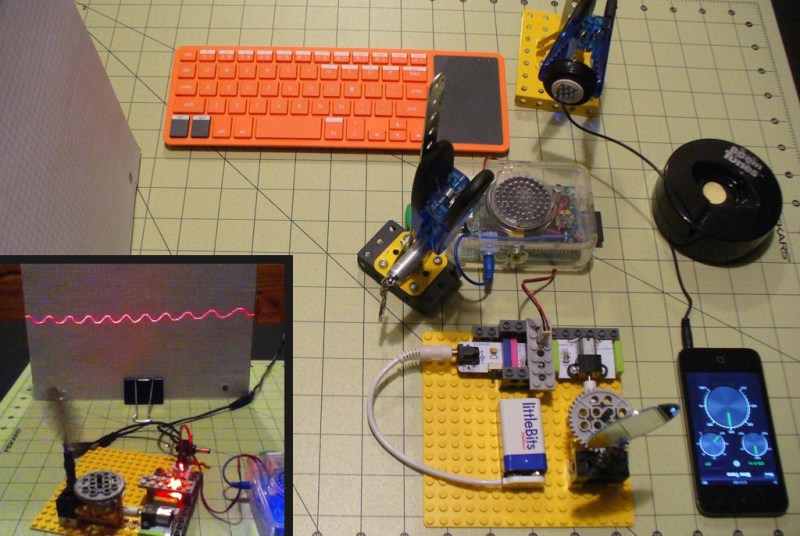
[Steve]’s scope is built out of a hodgepodge of parts including Lego, an Erector set, LittleBits, and a Kano Computer (based on a Raspberry Pi). The Pi generates a PWM signal that controls the speed of a LittleBits motor. The motor is hooked up to a spinning mirror that sweeps the laser across some graph paper, creating a straight laser line.
After he got his sweep working, [Steve] took a small speaker and mounted a mirror to its cone. Next he mounted the speaker so the laser’s beam hits the mirror on the speaker, the spinning sweep mirror, and finally the graph paper display. The scope’s input signal (in this case, audio from a phone) is fed into the speaker which deflects the laser beam up and down as it is swept across the paper, forming a nice oscilloscope-like trace.
While [Steve]’s scope might not be incredibly usable in most cases, it’s still a great proof of concept and a good way to learn how old oscilloscopes work. Check out the video after the break to see the laser scope in action.


Raspberry Pi and PWM? Pssh!
http://www.allaboutcircuits.com/vol_6/chpt_3/11.html
Do it in analog “like a boss”! You can get your frequency response in to the low Ghz if you heterodyne dat shit:
http://www.radio-electronics.com/info/rf-technology-design/mixers/double-balanced-mixer-tutorial.php
I don’t think the laser can spin beyond a few thousand rpm, the pi is pretty good for that setup.
What is this keyboard ? Seems to be compact.
Nice article, thanks for sharing.
I opened this article to ask the exact same question!
Interesting article.
http://us.kano.me/
comes with a raspberry pi kit. 150$
I’m not sure of the model he has, but there are dozens of mini and micro keyboards available. I use one from Gearhead for my Pi running XBMC in the living room.
We need an edit button for replies.. =/
http://ak1.ostkcdn.com/images/products/4727615/Gear-Head-KB3800TPW-Wireless-Desktop-Keyboard-94990dc6-b729-4604-a1ae-fb4435ea4468_320.jpg
An EDIT button, now why didn’t I think of that }:¬) … me and 116 other people… https://www.google.co.uk/?gfe_rd=cr&ei=A3sNVb7VC8iq8wfBtIGwAw&gws_rd=ssl#q=%22edit+button%22+site:hackaday.com
https://www.kickstarter.com/projects/alexklein/kano-a-computer-anyone-can-make
More of a waveform visualizer than an oscilloscope. The most important part of an Oscope is being able to measure voltages as well as frequency. Calibration is the key.
If he knows the scanning rate, he can determine frequency the same way we always have before scopes came on the scene that would do the measuring for us. The same is true with the voltage, so long as the ratio of volts per division is a known quantity, something that could be easily determined. I suspect that this is why he used graph paper as a background medium.
This is as much a true oscilloscope as any of the analog Tektronics scopes that I have owned over the years. Kudos to [Steve] for an excellent build, and extra credit for incorporating Lego. :)
Just picked up a Tek 2445 analog scope recently, it’s pretty awesome.
Nice scope!
http://hackaday.com/2012/03/26/dinos-one-year-extravaganza-is-a-laser-oscillograph/
pretty sweet and simple project to get you going in the right direction :)
What an incredibly complex way to do a simple task! A 32-bit computer with 512 MB of RAM and a multitasking operating system does nothing but blink an LED, which through an optocoupler and amplifier, drives a motor. This much could be done with a battery, a variable resistor, and a motor. And he didn’t just use a $30 Raspberry Pi, he used a $150 kit that includes an RPi for this task, in addition to at least $100 for Little Bits kit.
But all of that aside, I don’t understand why [Ethan Zonka] refers to this project as a “home-built ‘oscilloscope’ that works a lot like a simple analog oscilloscope”, when it IS in fact an analog oscilloscope, by pretty much any reasonable definition of ‘oscilloscope’.
I got ya covered, bro.
Does it have serial decoding? hows the FFT? does it have full ethernet connectivity?
kidding
nice little project
Heh, takes me back to middle school. Although the laser was a good deal bigger back then, and all I had was a pot for the motor speed. ;)
I don’t really get that speaker thing. Isn’t the mirror on the speaker supposed to be tilted up/down a bit in order to reflect laser to different positions on y-asix on the screen? Since the speaker can only push-out or pull-in the mirror linearly, how could the laser be reflected vertically?
It works because it’s attached off it’s center of mass, so the linear motion causes it to twist. But you’re right, you’d get a much better signal if you fixed one side as a hinge. (Tape works great IIRC)