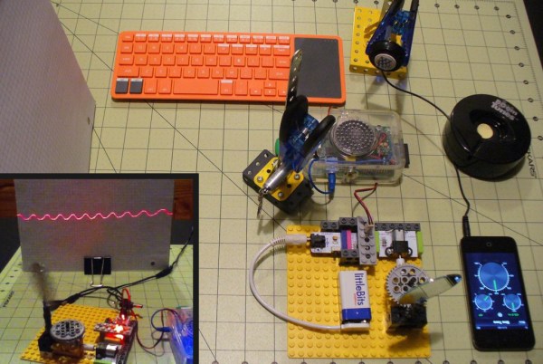
If you’ve ever used an old-school analog oscilloscope (an experience everyone should have!) you probably noticed that the trace is simply drawn by a beam that scans across the CRT at a constant rate, creating a straight line when there’s no signal. The input signal simply affects the y-component of the beam, deflecting it into the shape of your waveform. [Steve] wrote in to let us know about his home-built “oscilloscope” that works a lot like a simple analog oscilloscope, albeit with a laser instead of a CRT.
[Steve]’s scope is built out of a hodgepodge of parts including Lego, an Erector set, LittleBits, and a Kano Computer (based on a Raspberry Pi). The Pi generates a PWM signal that controls the speed of a LittleBits motor. The motor is hooked up to a spinning mirror that sweeps the laser across some graph paper, creating a straight laser line.
After he got his sweep working, [Steve] took a small speaker and mounted a mirror to its cone. Next he mounted the speaker so the laser’s beam hits the mirror on the speaker, the spinning sweep mirror, and finally the graph paper display. The scope’s input signal (in this case, audio from a phone) is fed into the speaker which deflects the laser beam up and down as it is swept across the paper, forming a nice oscilloscope-like trace.
While [Steve]’s scope might not be incredibly usable in most cases, it’s still a great proof of concept and a good way to learn how old oscilloscopes work. Check out the video after the break to see the laser scope in action.


