LED filaments started showing up in light bulbs a few months back. [Mike] discovered that the strips are available in bulk from ebay and Alibaba. Always keen to work with new LED technologies, [Mike] ordered a few for experimenting and posted the results on his [mikeselectricstuff] YouTube channel. He also added the information to his website.
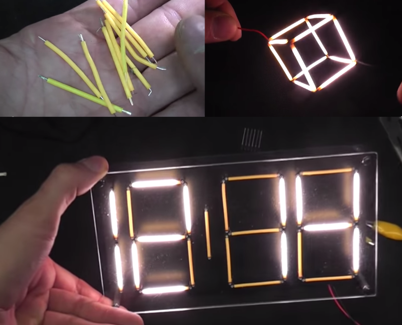
The filaments consist of 28 LEDs connected in series. The blue LEDs are covered by the typical yellow phosphors to make them glow white. It’s interesting to note that some of the filaments use a removable silicone sleeve to hold the phosphor coating, while others are coated with a resin material. The LEDs themselves are bare dies mounted to a metal strip and joined by bond wires. The entire strip can be bent, but be careful, or you’ll break the fragile bond wires.
The strips do require a fair bit of voltage to operate. The entire strip runs best at around 75 and 10~15 mA, while putting out about 1 Watt of light. [Mike] tested a strip to destruction by pumping 40 mA through it. Predictably the strip went out when the bond wires melted. The surprising part was that the strip blinked back on as the wires cooled and re-connected. The strip and wires were working as a temperature controlled switch, similar to the bimetalic strip found in old fashioned “twinkling” incandescent Christmas lights.
Not satisfied with simple tests, [Mike] went on to build a clock using the filaments as elements of a seven segment display. Inspired by numitron and minitron displays, [Mike] built a single sided PCB which held the clock circuit on the bottom and the LED filaments on top. The filaments are spaced off the board by tall wire wrap sockets, which proved to be difficult to keep from shorting out. Texas Instruments TPIC6B595 chips were used to control the LED filaments. Logically the chip functions the same as a 75LS595, which means it can be driven with a SPI bus. The open drain outputs can handle 50 volts – which makes them perfect for this application. The clock is tremendously bright, but there is still a bit of room for improvement. [Mike] notes that the phosphor of un-powered filaments tend to glow a bit due to light absorbed from nearby illuminated filaments. He’s experimenting with color filters to reduce this effect. At full power though, [Mike] says this clock would easily be daylight readable, and we don’t doubt it!
[Mike’s] final test was a bit whimsical – he built a cube entirely from the LED filaments. The cube looks awesome, but we can’t wait to see who will move things into the 4th dimension and build a tesseract!
Thanks for the tip [ZoomZoomLuke]


Does it annoy anyone else that people say “leads” instead of “L.E.D.’s”?
Yes
Yes
In that no one around hear says lead for LED it’s odd to hear it, but still some of life’s small stuff not to sweat
It’s all small stuff, but this is among the smallest.
Yes
I’ve never understood why so many people say “ell ee dee”. instead of LED, less so why anyone has a problem with it.
Nobody ever spells out acronyms like ROM, RAM, EPROM, FAT etc. so why should LEDs be any different? It’s not like there’s any risk of confusing it with the metal or the past tense of the verb “to lead”.
Think of all the time you waste spelling it out – I’d waste a good few minutes a year that I could be using to take stuff apart.
Or to make that ( this ?) point? :)
Inspiring though. I salvaged a butt load of LED strips, rolls actually, waterproof and adhesive backed (peel and stick ) mostly rgb. Think I’m gonna have to take a few apart now.
“konnect it 2 the leed”
“wut leed? the battery leed or the light emitting diode”
taking advantage of language and enunciation for granted now.
plz tell us you are old enough to have remembered saying “double-yew double-yew double-yew”.
“I found an awesome windows command that pings every hop called TrAcEr-Tee”
“uh, you mean the old unix command called trace route?”
-=-=-
We call them “El-Eee-Dees”. because connecting a “lead fishing wieght to a lead battery lead may have led to the lead on the led burning out” keeps us from sounding like a retarded electronics hipster speaking engrish with a risp.
Leed vs ledd, boyo.
You win the internet for today.
I say “ell ee dee”, but also say oh-lead.
Not as much as this…. “The entire strip runs best at around 75 and 10~15 mA”
75 goats? 75 Degrees? 75 Millirads? Oh I know it wants 75 hogheads!
75 Hads (Hackaday approximative deceiving system), a very common unit here.
I have never heard them called “leads”(like the wires). I however have heard them called “leds” (like the metal). the context of the sentence is usually enough to tell if the speaker is referring to the bulb or the metal, since no one with halfway decent grammar would say connect the lead (metal) to the battery.
Dr. Stiffler always called them that in all of his videos. I, of course, have never done so in any of my videos. To each his/her own I suppose. As long as there is no doubt as to what is being talked about, then I guess it does not matter.
The other sleve material is (rubbery) silicone, not (brittle) silicon. Was this a typo or a misunderstanding? [Mike] clearly says silicone.
It’s certainly silicone, but approximately zero people actually know the difference and use the terms correctly. I’d say the misuse is about as widespread as using “literally” to mean “figuratively.”
Fixed. Obviously everyone aroundbhere knows the difference. Thanks for pointing out the typo.
Damn b key on cellphones! I do that all the time too.
Yeah that one literally causes a mold irritation, which in turn causes a slight increase in blood pressure, which if left unchecked will produce a tension headache.
That I blow totally out of proportion.
I think we have a NEW winner of the Internet for today . . . .
“The entire strip runs best at around 75”. Degrees, VAC, VDC or gerbils on wheels?
would love to add to the snarky a little bit-
1 watt of what kind of light? incandescent? fluorescent? neon? led?
lumens seems like the only fair way to compare apple light with banana light, when dealing with led linearly lumens per foot is clear.
Green and yellow tinted LEDs get more lumens per watt than white or blue.
For general lighting, the color temperature and Ra or CRI value should be mentioned as well to make a meaningful comparison.
1 watt of power consumed, obviously
With the power efficiencies of the best LEDs running in excess of 70%, 1 watt of visible light energy from a string of LEDs is not out of the question. Whether the power was input or output really should have been clearly specified.
And [zhanx] proudly declares himself a member of the “I’m not bright enough to figure out something simple” club.
Don’t worry son, it’s a big club.
“so many. so many.”
okay, can you just say does it run at 75 kilometers per hour or miles per hour.
Did you forget everything from middle school? When writing an essay your state the first acronym you use in full wording.
Anthony… Tsk. tsk. tsk. Son. I am disappoint. He didn’t even say the acronym ffs!
https://s-media-cache-ak0.pinimg.com/236x/e8/84/93/e8849370ec5e2f71464a275b72e73cc8.jpg
…and 75 was said in what context?
If the context is clear enough, then the rest doesn’t matter.
For example I’ve no idea what context surrounds that lame meme you’ve put so much effort into posting, so the point you’re trying to make is lost.
Unlike what ’75’ means.
any idea how that coverts to # of snakes on a plane?
VDC, he mentioned positive side.
Gerbils. These strips require 75 gerbils, so that clock has hundreds in the background making it work. I want to see how he silenced the little wheels!
Oh, no, no, no. That’s only if you wire the strands in series. If you put them in parallel, you can run a few strands off of 75 gerbils.
Come on… Everyone knows gerbils are only rated to 20mA.
Not European Gerbils. They are now rated to 32.6 mA’s ever since that terrible fire back in 2013.
The cube reminds me of the well known physics puzzle about the cube of resistors.
Exactly what I was thinking. The resistor cube is discussed in “the art of electronics”.
Then I started wondering about an octahedron, dodecahedron, iconsahedron, and other platonic solids.
I was wondering: which of these could be lit by a single input and output voltage wire?
Consider the graph of your solid. Based on the square we assume a vertex connects all sides. If a side has both vertices equidistant from one of the end vertices you can’t light it with a single input, since the potential difference at that vertex is zero.
However, if you consider having insulated junctions at each vertex you could find shapes with either a series of paths of equal length from one node to another, a single path from one node to another, or a single circuit traversing all sides and returning to the starting vertex. Such a circuit could illuminate e.g. an octahedron.
Watt of light.
Nooooooooo!
I know I’m being a unit-pedant, but I’d really love to see people use lumens. Comparing between lighting technologies is sticky enough without bringing James into it.
Having said that, these things are fun, and I love seeing HaD review novel lighting implementations. I still want some of those RGB 7-segment displays.
Trouble is, measuring lumens is not a trivial task.
If you assume that leds of a similar generation have a similar lumens-per-watt, then saying it’s a “1 watt” led is at least getting you in the ballpark of “what to expect”, assuming a sensible driving circuit.
But once you’ve characterized a light emitter, it’s just a constant multiplier to convert from watts to lumens or vice-versa. Cliff must REALLY get annoyed when he goes shopping for light bulbs, where everything is sold by its equivalent in incandescent watts.
Lumen is a purely subjective unit. It’s normalized to an ideal human eye. So while useful for comparing reading lights if you’re comparing lights for anything other than human visibility it’s a moderately useless unit.
Sure, Watts are less than ideal but if it’s watts of radiant flux rather than watts of electric power that’s a bit more usefull across the board. In designing circuits, watts of electric power are of immediate concern.
What exactly is the use for an electric lamp other than human vision?
Knowing the watts of electricity in and the watts of light out makes it easy to determine both energy efficiency and the watts of heat that must be dissipated somehow. I much prefer the use of watts to specify light.
Wow, folks sure are splitting a lot of hairs in the comments tonight…
Is a split hair an SI unit or imperial?
Ginger or blonde?
Curtains or carpet?
There’s carpet?
Relevant
https://imgs.xkcd.com/comics/drapes.png
Ginger or MaryAnne?
75V at 10-15ma? If you wanted to power this purely using batteries, would it be possible to attain a similar degree of lumens as the original setup (75V @10-15mA) using a AA or maybe a 9V battery but with higher amps? (maybe around 20-30 mA)?
Nope, if you want to have higher current, you must provide higher voltage. It’s like with rivers, if you want water to flow faster, you need bigger level difference.
Thanks a bunch for the reply!!
It’s a pity these can’t be used in mobile applications. These would have been perfect if it wasn’t for the high voltage req.
LEDs are in series, 20 x ~3.6v LEDs gives you the 75 volts.
You can buy DC-DC regulators that will boost 3-15v to 75v.
Yes, because that’s so much more efficient than just directly driving a shorter series of LEDs…
Just throw a DC/DC step-up converter at them and you can make it run from an AA battery (at 1A, so it won’t work long)
Just to play devil’s advocate — yes, you could trade off current for voltage if you were able to get into the chips and wire them up in parallel instead of series. At least I’m assuming it’s a whole pile of diodes in series inside…that’s the only way that 75 volts makes sense.
Or you could use a switching boost converter, but stepping up from even a 9v battery to 75v is pretty insane.
It wouldn’t be 20 or 30 mA, though. 15mA @ 75V ~= 125mA @ 9v, or 750mA @ 1.5v.
the 15 mA is, I think, what they run at when made into a light bulb. This would be WAY overkill for a 7-segment display – you wouldn’t be able to look at it. Probably 1 mA would be sufficient for use as an indicator.
Trolls will troll. Nice work as always by Mike. Let the unwashed figure out the details by LISTENING to the video.
I’m hearing-impared, you insensitive clod!
Well, auditory processing disorder, but same challenge.
Cool. Never seen a “filament” design before. Other shapes like squares, circles, strips, domes and bulbs have been available for a while now, check out Chromalit at Future Electronics. They make good diffusers, and will blend in other colors unchanged if needed to tweak white balance.
It’s worth mentioning here that if you’re looking for a handful of these things, search for “COB filament” or all you’ll get will be car lights and filament doodling pens – the COB (“Chip On Board”) term was a new one for me.
(http://www.prophotonix.com/resources/Technical-Overviews/led-array-methods.aspx)
Regarding that cube – what easiest solution would be to power something like this (or more complex shapes) from ordinary 220(230)V AC outlet (or better ceiling lamp)? Connect in parallel and find 70v AC->DC power supply (is there anything comparable to these cheap to-12v ones?)?
I just got some of these as well, but they’re completely inflexible, almost as if they are in some kind of glass tube.
A lower-voltage version could be used to make the ULTIMATE Uncle Fester Magic Light Bulb (much better than hiding ordinary LEDs in a frosted bulb). Otherwise, it would take some determined hacking to get a powerful-enough battery and 70V inverter into an Edison base. Hmm… There’s a challenge for this crowd! I’ll bet the first creator could make some serious money with it, especially around Halloween. Hint: turn it on & off with a low leakage current through the contacts, so that it can be activated by a tongue or wet finger. Use the base from a three-way lamp to get an extra contact for charging the battery.
Bigger challenge: Find/make a replacement LED strip that operates on 5V. Or, create a version using EL wires–it wouldn’t be nearly as impressive since it wouldn’t be very bright, but the battery life would be much longer.
10 years late but I did that back when the series was aired. Almost 60 years ago? Broke out the glass terminal and one AA and bulb fit inside with a press tongue on the end to make contact. It was a hit in school.
I feel like I stumbled into an asylum with a million people suddenly not understanding very plain simple words,,as well as everybody ignoring the whole subject and obsessing with random words instead
For most commenters: I meant an ‘insane asylum’, thanks for caring to know what I meant with the word asylum..
Just to add some useful information to this grammar class, be wary of buying these from China. I just bought a batch that listed as DC when they were in fact AC making them totally useless for my application.
AC LED filaments? …they ran two sets of diodes in opposite directions down each filament or… Wha..?
Yup. Pretty sure this is done to double light output for same power usage as half the leds are off every half a cycle.
Little tip, depending on which emitters are used they sometimes need less than 75v or more on longer samples. I have one here which lights up just from gm counter hv module once the sealed bulb was removed. For maximum lifetime it does need active cooling at any significant current; had a crazy idea to make a monster emitter using hundreds layered behind sheet of glass with heat conductive gel sheet behind on a copper heatsink/ fan robbed from 1st gen Core laptop.
And for maximum light output coupling use uv nail varnish from boots. This works well for fine interconnects too as it sets hard so you can connect wires to bare silicon or other FUN Stuff
Anyone have experience with parallel LED filaments?
I’ve looked all over and no one seems to sell them, yet I’ve bought 2 sets of solar lights with 10 bulbs (also in parallel), custom made? The base of the bulb says 3V, each bulb with a single LED filament, each with 18 chips.
It’s powered by a tiny solar panel charging a single 1.2V AA boosted to ~3V at a whopping 100mA and are very dim, I tried to run the string at 5V and they were drawing 400mA, then switched to a CC driver at 300mA and ran fine too, can I go higher or would I risk killing them?
Each bulb has a little resistor but I can’t make out it’s color/value without destroying it.
The usual series LED filaments are rated 60V/10mA with like 28chips..that means in theory, I could run each bulb at 180mA?! (with infinite cooling), doubt these are filled with gas to aid cooling though.
Accidentally broke a bulb than a second one, got a 3rd set as spares, the LED filament has a Vf of 2.54V and a 47ohm resistor, drawing 10mA at 3V, powering them with a buck boost at 3.3V (MT3608 based) off a single 18650 cell. Modified the DC-DC converter to 3.5V and it seems to be fine at 20mA, the 20 bulbs would be drawing 400mA, which is about the maximum the MT3608 can handle while boosting < 3.5V.
Cut a trace and added a 5.6k resistor to the 100k:
Vref 0.6 x (1+105.6k/22k)=3.5V
Charging is handled by a CN3791 connected to a 12V/7W solar panel.
Yes, its helium apparently.
The emitters use this due to the mean free path of He being very long.
Interestingly the broken filaments sometimes can be fixed with care, I found that low melting point In alloy works fine for joints and silver conductive paint (shake well!!!) for the fine stuff.
You can find 3 V and 12 V versions now.