A lot of projects get made because someone just has the parts lying around. In this case, [Ed Nisley] got given a nice 8×8 RGB LED matrix, and needed something to display. [Ed] details the transformation of stuff-lying-on-the-desk into a unique matrix display for a Geiger counter (which he also presumably had sitting around somewhere). The result is a lightshow that’s as random as radioactive decay, and that’s pretty darn random.
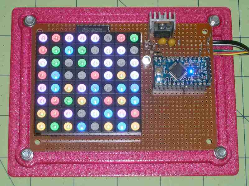
 The first post covers the hardware layout. It’s build on protoboard, but ends up looking a lot nicer than our projects because [Ed] spent some time hiding the shift-register ICs and row-driver transistors underneath the matrix itself, which was nicely socketed above. A sweet touch is the use of SMT resistors soldered upright underneath the board to save space. Cute.
The second post covers the circuit design, and is worth a look if you’re new to driving many LEDs from a minimum number of microcontroller pins. There are eight rows, and three colors each for eight LEDs per row. Without using shift registers, this would require 8*8*8*8 = way too many pins to control. If you want a worked example of how to do this with just four microcontroller pins, have a look. (Spoiler: cascaded shift registers driven by the AVR’s hardware SPI peripheral.)
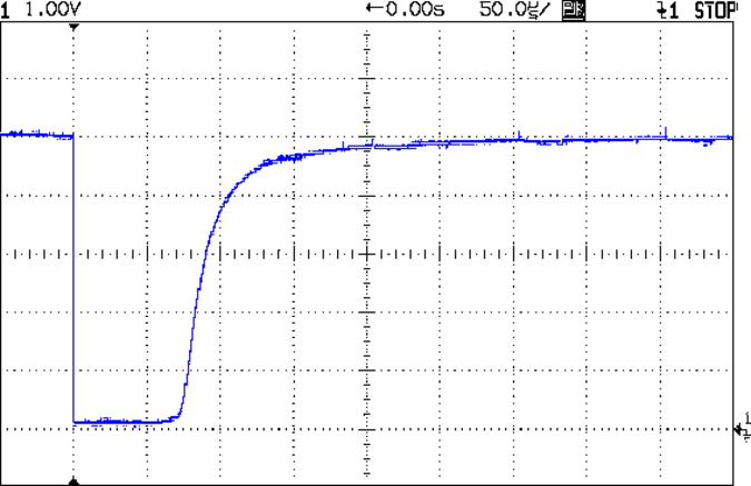
The third post starts to flesh out the software. [Ed] settled on seven colors (and off) for the display, so the matrix’s total state can be crammed into just 32 bytes, which fits nicely in even a tiny microcontroller, much less the gargantuan ATmega328. Wrapping this all up in an array of structs and providing a couple of helper functions makes quick work of the software side. The addition of a sync pulse to trigger an oscilloscope at the end of a row is a nice touch.
 Next up is the Geiger counter interface software post. When a radioactive decay event is detected, the code reads out the time in milliseconds and uses that as the source of randomness. To whiten the noise, the times are run through a simple hash function: the Jenkins hash (link). This hash function was new to us and seems pretty useful for quick-and-dirty microcontroller applications.
The last post details pre-loading the matrix on startup and running a test sequence that blinks each LED to make sure they’re all working. Using a single random value to seed a software pseudo-random number generator ensures that it will (almost) never start off with the same display twice.
Phswew! That’s a lot of well-documented writeup of a well-polished project! Hope it inspires you to dig out something cool from your junk drawer and build.


I like this guy’s style. After the apocalypse, everyone else is going to be staggering around with gloomy, industrial-looking geiger-counters, but he’s going to have the world’s only festive party geiger-counter. That’s the spirit. When life gives you nuclear winter, turn it into nuclear Christmas.
well said :)
For some reason i though of this “When life gives you lemons, don’t make lemonade. Make life take the lemons back! Get mad! I don’t want your damn lemons, what the hell am I supposed to do with these? Demand to see life’s manager! Make life rue the day it thought it could give Cave Johnson lemons! Do you know who I am? I’m the man who’s gonna burn your house down! With the lemons! I’m gonna get my engineers to invent a combustible lemon that burns your house down!”
If life ever gives you melons, you could be dyslexic.
i lol’d hard at this
It will make an easier target.
The Jenkins hash link is not there.
this is pretty cool. I like the RGB LED Matrix Module, but I don’t like that there’s no real one-chip solution to driving it like the MAX7221 is for the monochrome version of the 8×8 LED Module…
I actually put a board together similar to this and was thinking about submitting to hack-a-day, but [Ed Nisley] beat me to it. now it just looks like I’m copying him..
though, he actually put his to use, and his code looks a lot better than anything I could have written up, so great job!
maybe I’ll improve on my design, find an application and submit it then. you can see my work as it is here:
http://thetimmy.silvernight.org/images/rgbledmodule/
Radioactive decay is a stochastic process (random). However, to use it as a source of randomness care must be taken because of its non-uniform distribution (Poisson distribution to be precise). One needs to find out the sampling period for which the probability of a single event is exactly 50% and keep watching it. Otherwise such random generator will be biased.
It doesn’t matter for this application. It’s just for fun.