The Hackaday Prize: An Ultra Low Cost 3D Printer Controller

This isn’t a Hackaday Prize entry that will change the world, but that doesn’t mean there’s not a place for it. [vdirienzo] is building an ultra low-cost 3D printer controller for 3D printers and other CNC machine. It’s not going to change the world, but it is a rather interesting little device.

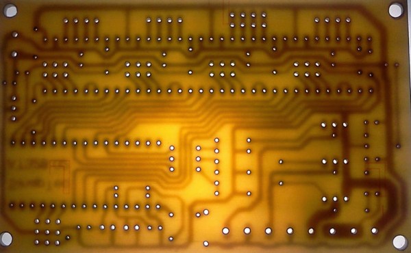
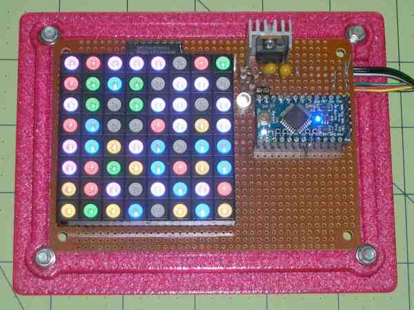
This printer controller is very minimal, with a single-sided circuit board with just enough parts and components to make this board useful. The stepper motor drivers are from Pololu, and most of the other components are stuff you could pull out of a reasonably stocked junk drawer. The microcontroller is rather interesting; it’s an Arduino Nano. Instead of the ATMega644 and ‘Mega1280 microcontrollers found on other 8-bit printer controller boards, [vdirienzo] slimmed down the Teacup firmware to fit on the ATMega328 in the Arduino Nano.

The SinapTec is not by any means the first effort to create an ultra low-cost controller board for a 3D printer that can be assembled at home. The RepRap Gen 7 electronics can be manufactured on a RepRap or small CNC mill. There’s not much to these boards – just a small, single-sided board. If you want a small, simple, and cheap controller board for a 3D printer, this is all you need.

While a cheap 3D printer controller board doesn’t really fit with the ‘change the world’ theme of The Hackaday Prize, that doesn’t mean there’s still not a place in the contest for [vdirienzo]’s entry; we have a Best Product category, with a $100k prize and a six month residency in the Hackaday Design Lab. If that’s not enough reason to build something cool – even if it won’t change the world – we don’t know what is.


The 2015 Hackaday Prize is sponsored by:

Covert Remote Protest Transmitters

As a piece of protest art, “Covert Remote Protest Transmitters” ticks all the boxes. An outdoor covert projector that displayed anti-globalization messages at a G20 summit is protest. To disguise it inside a surveillance camera body housing — sticking it to the man from inside one of his own tools — is art. And a nice hack.

However you feel about the politics of globalization (and frankly, we’re stoked to be able to get cheap tech from anywhere in the world) the open-source DIY guidebook to building the rig (PDF) makes up for it all.

They installed the camera/projector long before the summit, where it sat dormant on a wall. A cell phone inside turned on the projector’s light with each ring because they attached a relay to the cell phone’s speaker circuit. In the instructions there’s an example of using a light-dependent resistor (CdS cell) to do the same thing, relying on the phone’s backlight functionality instead. There are a lot of ways to go here.

The optics consist of a couple of lenses aligned by trial and error, then fixed in place to a balsa wood frame with hot glue. A big fat Cree LED and driver provide the photons.

The video documentation of the piece is great. It’s mostly the news media reacting to the art piece as a “security breach”. A security breach would be a gun or a bomb. This was an overhead projector displaying messages that were out of the organizers’ control. Equating security with the supression of dissent is double-plus-ungood. Touché, CRPT.

Anyway, while you’re getting prepped for your next protest, have a look at the Image Fulgurator.

Sea Rendering

Project Sea Rendering Autonomously Renders Sea Bottoms

[Geir] has created a pretty neat device, it’s actually his second version of an autonomous boat that maps the depths of lakes and ponds. He calls it the Sea Rendering. The project is pretty serious as the hull was specially made of fiberglass. The propulsion is a simple DC motor and the rudder is powered by an RC servo. A light and flag adorn the top deck making the small craft visible to other larger boats that may be passing by. Seven batteries are responsible for all of the power requirements.

Sea Rendering

The craft’s course is pre-programmed in Mission Planner and uses ArduPilot loaded on an Arduino to steer to the defined way points. An onboard GPS module determines the position of the boat while a transducer measures the depth of the water. Both position and depth values are then saved to an SD card. Those values can later be imported into a software called Dr Depth that generates a topographic map of the water-covered floor.

[Geir] has sent this bad boy out on an 18 km journey passing through 337 way points. That’s pretty impressive! He estimates that the expected run time is 24 hours at a top speed of 3 km/h, meaning it could potentially travel 72 km on a single charge while taking 700 depth measurements during the voyage.

Continue reading “Project Sea Rendering Autonomously Renders Sea Bottoms”

The Biggest Game Boy Ever?

Feeling nostalgic? Miss the solid feel of an original Nintendo Game Boy? You could smash a window with one and keep playing Pokemon the whole time!  Well, [Raz] was, and he built what might just be the biggest Gameboy ever. Gameboy XXL: The Texas Edition.

Actually, it was commissioned for a Belgian music festival called Nintendoom — picture video game music + rave. Anyway, the organizer thought it would be so cool to have a giant functional Game Boy, so [Raz] got to work. He made it out of 10 square meters of 3mm thick MDF, which he laser cut into shape at the Brussels FabLab. The electronics inside consist of a 19″ LCD monitor, a Raspberry Pi, and a few jumbo size buttons.

It’s pretty freaking awesome. It runs Retropie which allows you to play pretty much whatever game you want. Check it out after the break.

Continue reading “The Biggest Game Boy Ever?”

Need Timing Diagrams? Try Wavedrom

When working with anything digital, you’re going to end up reading or writing a timing diagram before long. For us, that’s meant keeping (text) notes, drawing something on a napkin, or using a tool like Inkscape. None of these are ideal.

An afternoon’s search for a better tool ended up with Wavedrom.

Just so you know where we’re coming from, here’s our list of desiderata for a timing diagram drawing solution:

  • Diagrams have a text-based representation, so their generation can be easily scripted and the results versioned and tracked throughout project development
  • Command-line rendering of images, because we like to automate everything
  • Looks good
  • Simple to use for common cases, but flexible enough to do some strange stuff when needed
  • Output modifiable when absolutely necessary: SVG would be nice

Basically, what we want is graphviz for timing diagrams.

Wavedrom nails four out of these five at the moment, and has promise to cover all of the bases. Give the online editor demo a try. We found it intuitive enough that we could make simple diagrams without even reading the fine manual. The tutorial has got you covered for more esoteric use cases.

foo

Clearly, some good thought has been put into the waveform description language, WaveJSON; it’s mostly readable and makes the essentials quick and easy. Because you can also enter straight SVG, it leaves the door open for full-fledged lunacy.

Wavedrom is written in JavaScript, and built for embedding in webpages; that’s the way they intend us to use it. On the other hand, if you want to run your own local version of the online editor, you can download it and install it locally if you’d like.

Our only quibble is that the standalone, command-line application wouldn’t generate images without the GUI on our Arch system. (Looks like there are some Google Chrome dependencies?) Otherwise, we think we’ve found our solution.

There are other applications out there. Drawtiming looks good, but we can’t quite get our head around the file format and the graphic output isn’t as flexible as we’d like: it only outputs GIF and we’re more into SVG because it can be edited easily after the fact.

There are font-based solutions that let you “type” the timing diagrams. We found Xwave and “Timing Diagram Font“. These work but aren’t particularly flexible; if you want something to happen at odd times, you’re out of luck. Plus, it just feels like a dirty hack, as if that were a bad thing.

Latex users can use tikz-timing, which makes sketching out your timing diagrams as much fun as laying out a very complex table in Latex (that is: not fun at all). On the other hand, it looks good, is ultimately flexible, outputs PDF, and would be scriptable if someone put the time in to write a nice frontend.

So for the next little while, we’re trying out Wavedrom.

What do you use for making timing diagrams?

LED Matrix Plus Geiger Counter

A lot of projects get made because someone just has the parts lying around. In this case, [Ed Nisley] got given a nice 8×8 RGB LED matrix, and needed something to display. [Ed] details the transformation of stuff-lying-on-the-desk into a unique matrix display for a Geiger counter (which he also presumably had sitting around somewhere). The result is a lightshow that’s as random as radioactive decay, and that’s pretty darn random.

img_5583-random-led-dots-circuit-layout-rb-smd-resistorsThe first post covers the hardware layout. It’s build on protoboard, but ends up looking a lot nicer than our projects because [Ed] spent some time hiding the shift-register ICs and row-driver transistors underneath the matrix itself, which was nicely socketed above. A sweet touch is the use of SMT resistors soldered upright underneath the board to save space. Cute.

The second post covers the circuit design, and is worth a look if you’re new to driving many LEDs from a minimum number of microcontroller pins. There are eight rows, and three colors each for eight LEDs per row. Without using shift registers, this would require 8*8*8*8 = way too many pins to control. If you want a worked example of how to do this with just four microcontroller pins, have a look. (Spoiler: cascaded shift registers driven by the AVR’s hardware SPI peripheral.)

The third post starts to flesh out the software. [Ed] settled on seven colors (and off) for the display, so the matrix’s total state can be crammed into just 32 bytes, which fits nicely in even a tiny microcontroller, much less the gargantuan ATmega328. Wrapping this all up in an array of structs and providing a couple of helper functions makes quick work of the software side. The addition of a sync pulse to trigger an oscilloscope at the end of a row is a nice touch.

aware-rm-60-geiger-pulseNext up is the Geiger counter interface software post. When a radioactive decay event is detected, the code reads out the time in milliseconds and uses that as the source of randomness. To whiten the noise, the times are run through a simple hash function: the Jenkins hash (link). This hash function was new to us and seems pretty useful for quick-and-dirty microcontroller applications.

The last post details pre-loading the matrix on startup and running a test sequence that blinks each LED to make sure they’re all working. Using a single random value to seed a software pseudo-random number generator ensures that it will (almost) never start off with the same display twice.

Phswew! That’s a lot of well-documented writeup of a well-polished project! Hope it inspires you to dig out something cool from your junk drawer and build.

Cable Vise

New Cable-Based Vise Improves Woodworking Workshop

We are all aware of the typical wood shop vice, the type that is mounted underneath the workbench and takes forever to open and close by continuously spinning a large handle. These vises normally only open several inches due to the length of the operating screw. They are also not very wide because a cantilevered wide jaw would provide less force the further away it is from the center-mounted operating screw.

Cable Vise
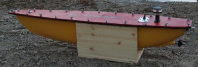
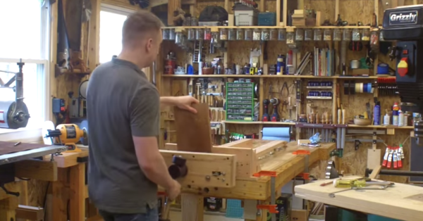
Wood worker [Andrew] wanted a very versatile and large vise for his shop. It needed to be wide, provide equal clamping force along the jaw and be able to hold very thick objects as well. One more thing, he wanted it to have a quick release clamping system so there would be none of that continuous handle spinning nonsense.

Spoiler Alert: [Andrew] did it! The end product is great but the interesting part is the journey he had taken along the way. There were 4 revisions to the design, each one making the vise just a bit better.

Continue reading “New Cable-Based Vise Improves Woodworking Workshop”