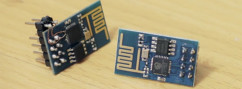
The ESP8266 is an incredible piece of hardware; it’s a WiFi module controllable over a serial port, it’s five freaking dollars, and if that’s not enough, there’s a microcontroller on board. Until there’s a new radio standard, this is the Internet Of Things module.
The most common version of the ESP, the -01 version, only has a 2×4 row of pins for serial, power, configuration, and two lines of GPIO. It’s a shame that module only has two GPIOs, but if you’re good enough with a soldering iron you can get a few more. It took a lot of careful soldering, but [Hugatry] managed to break out two more GPIOs on this tiny module.
According to [Hugatry] a lot of patience to solder those wires onto those tiny pads, but after finishing this little proof of concept he discovered a Russian hacker managed to tap into four extra GPIOs on the ESP8266-01 module (Google Translatrix).
As a proof of concept, it’s great, but there’s more than one ESP module out there. If you’re looking for a cheap WiFi module, check out the ESP-03, -04, or -07; they have nice castellated pins that are exceptionally easy to solder to.
Video below.


Doing that sort of soldering is my day job. Nice to see someone doing the same thing out there.
What is your day job?
I did the same when i was working in a datarecovery lab some years ago..
I really enjoyed that.
I work for a VFD & soft-starters making company (WEG, in Brazil) in the R&D department.
Need some tips on soldering please. I too have these boards but am intimidated about ruining the board with inferior soldering skills
Having deadbugged a ATTiny85 QFN this looks like cake. Maybe it’s time for me to pickup a few of these guys.
Or get ESP-07 module ;)
Look at the ESP-12 module 9-digital I/O, 1-analog inout (0-1v). You can get them for $2.50 each free shipping from Aliexpress. For those not interested in SMT soldering anyway.
SMT -> SMD, fat fingers
well SMT is the proper term XP
I wonder if there is a ‘Kevin Bacon’ distance for TLA?
I guess it is would be at worst three…
free functionality via tapping into pins on chips is good stuff.
some usb sound chips have spdif pins for the taking; some even have i2s outputs. open the dongle, tap into the pins and run your digital audio out.
if that’s the only way to get features, then I see the value in it. otoh, if you can easily buy the module with the pins already broken-out, that’s the better way to go longer-term. or, if you have to make more than one of the things.
With a bit of practice 0.5mm pin spacing is not too bad, same spacing as the SA1100 StrongARM CPU’s. Wind a piece of thin copper around the soldering tip, and cut this at about 5mm. That will give you a nice point, if your soldering equipment is not suitable for this kind of work.
(They could have fit a 4 pin larger connector on the same PCB size, or at least provide a few easy to solder test points :-)
The easiest way to get a lot more GPIOs is by adding a shift register like the 74HC595. They are available on Aliexpress – 10 pack for $0.70 shipped. You can even chain 74HC595s. Use a couple of ESP8266 GPIO to control and load the 74HC595.
You are half right. You would get more outputs at the expense of all of your inputs.
Doesn’t have to be all. With a few passive support components it’s easy to do it all with one pin by taking longer to shift out the data.
http://romanblack.com/shift1.htm
Why not just solder directly to the 8266 pins??
Quite messy solution. I would rather use ESP-07 or ESP-12. And if you need more I/O lines – use I2C expander. ;)
Yes, I’m using MCP23017, it give me 16 i/o using I2C bus, easily hooked up on any ESPs (including ESP01).
Hi .i am very new to electronics things. i have been working on the same project for more than 2 months,, i need a guidance and wants to learn new things .. but just now its about ESP8266-12E and MCP23017.
i have posted my question on stack too. i hope i can get a help from you.
http://arduino.stackexchange.com/questions/34290/esp8266-12e-and-mcp23017-unable-to-identify-the-application
Tx and Rx can be used for GPIO as well.
Wouldn’t interfere on reprogramming(native, not lua)?
Russian “hacker” ha re-posted Dave Allan and Peter Scargill blogs only.
Alternatively, you could use Olimex’s ESP8266 breakout board, and get all the signals exposed from the get-go.
I would never tell someone not to explore the possibilities of their mind and skill, but the esp-12e is $3.80, fcc approved and already has all the pics broken out. The experiment is noble and an incredible learning process, but practicality is not there.
Also, I2C is a nice option. I am currently playing with a PN532 RFID reader via i2c and since it’s a bus, it’s always easy to add more I2C devices to the same two lines.
where I purchased NodeMcu+motor shield+wificar
http://goo.gl/jKNYgT
Some Documentation I found online:
ESP8266 NodeMcu Dev: http://doit-nodemcu-dev.doit.am/
ESP8266 NodeMcu Motor: http://doit-nodemcu-motor.doit.am/
NodeMcu Wifi Car: http://doit-nodemcu-car.doit.am/
WiFi Car Dev:http://doit-nodemcu.doit.am/index.html