Hackaday Prize Entry: A Braille Computer

As with all devices meant for a very small percentage of the population, computing equipment for the blind is very, very expensive. A Braille typewriter – a relatively simple machine that puts dots on a piece of paper – costs about $700 USD. Need a Braille interface for a computer? You can buy a 16-cell wide Braille output for $1600, and high-end models with an integrated keyboard go up to $5000.

For his Hackaday Prize entry, [Haydn Jones] is building a simpler and cheaper Braille computer. It’s not just a single line of text at a time; this computer will have a display that will output an entire page of Braille at a time.

The current solutions for a computer to Braille interface use small electromechanical cells for each character. That’s six individual pins for each character, multiplied by the number of cells on the display. Doing a full-page display with this type of mechanism, but [Haydn] has another idea. Instead of controlling each pin individually, all of the pins on the display will be controlled by a CNC-like mechanism. The pins themselves will be mechanical SR latches, better known as the mechanism in a ball point pen.

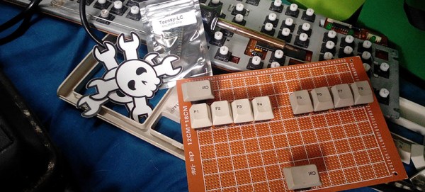
A display is only half of the IO of a computer, and for the input portion of his build, [Haydn] is also building a Braille keyboard. This doubles as a binary or hexadecimal keyboard, but the idea is very similar to a proper chorded Braille keyboard. It’s a simple enough build; just a few key switches and a microcontroller.


The 2015 Hackaday Prize is sponsored by:

homemade table saw

Homemade Table Saw Starts With Circular Saw

How often do us tinkerers go out into our basement/garage shop and don’t have the correct tool for the job? Most would say it happens more often than they would prefer. One option would be to buy the tool, but it is always more fun to build what you need! [kadambi] was in need of a table saw and decided to build his own.

He’s using a circular saw as his starting point but this isn’t just any old circular saw. This one has a riving knife that prevents work piece kickback and human contact with the back of the spinning blade. The saw is mounted upside-down to a wooden table that is supported by a wooden box frame. The boxy frame has another function, it acts as a dust collector. A vacuum is ported into the box frame creating a low pressure condition and most of the sawdust is sucked into (and settles on) the bottom of the box. Only a small amount of dust makes its way into the vacuum, preventing otherwise inevitable filter clogs. Out front is an industrial on/off switch as well as a separate e-stop switch.

[kadambi] has done some test cuts and is happy with his saw’s performance. If you’re interested in more DIY table saws, check out this mini saw or feature-filled one.

Hackaday Links Column Banner

Hackaday Links: May 31, 2015

Back in the mid-70s, [Paul Horowitz] (who has an incredible Wikipedia entry, by the way) started teaching Physics 123 at Harvard. Simple electronic circuits, solving problems with silicon; simple stuff like that. His lecture and lab notes started getting a following, and after Xeroxing a few dozen copies, he realized he had written a book. It was The Art of Electronics, and Ladyada interviewed this master of hand drawn schematics. A great interview and great camera work, too.

Like hackathons? How about one at CERN? It’s happening October 2 through October 4. The aim this year is to have a humanitarian and social impact thanks to technology. The projects last year were very good; everything from cosmic ray detectors to a $10 inflatable fridge for field operations.

You want viral advertising for your movie? This is how you do viral advertising for your movie. It’s Hackerman’s Hacking Tutorials, and we’d really like to know how they did the 80s graphics with modern computers. It’s not like you can just go out and buy a Video Toaster these days…

Previously available only through group buys, the Flir Lepton module is now available at Digikey.

We have hit the singularity. We have stared into the abyss, and the abyss has stared into us. There was a kickstarter to fund a trailer for another, bigger kickstarter. Relevant xkcd right here.

The Tymkrs had a lamb roast, and what better way to do that than with a huge lathe? Put some charcoal on the ways, turn it at a low RPM, and eventually you’ll have a meal. Bonus points for the leaf blower manifold, a gold star for carving it with a sawzall.

Nixie Clock Uses Ingenious Software RTC

There’s something about Nixie Tube Clocks that keeps drawing hackers to build their own iterations, even if its been done a gazillion times before. Their depleting supply, and the high voltage drivers to control them, makes it all the more interesting. [Pete Mills], a veteran of several interesting projects, many of which we have featured here, is no exception and decided to build his own version of a Nixie Tube Clock, but with several nifty features.

To put it in a nut shell, his Clock uses Nixie tubes for display, has USB serial communication, temperature measurement, AC frequency measurement, time and date keeping with a software based RTC, software driven boost converter for the 175V DC nixie tube supply and a windows app for clock configuration.

The software based time keeping is pretty interesting. It is essentially a method to calibrate the crystal to more closely match real time, and some code to keep track of the time and date.  This obviously leads to a reduction in components and the spin-offs that comes with that; increased reliability, cost reduction, real estate savings. The RTC code can easily be ported to other clock projects irrespective of the display used. Besides keeping track of time and date, it can also account for leap years, and report the day of the week. A zero-crossing detector connected to the low-voltage transformer supply that powers the clock can also be used as an alternative way of keeping time.

When connected to a serial console over UART, the clock can report back many variables depending on the queries it receives. The high voltage DC needed to drive the Nixie tubes is generated using a simple boost converter controlled by the micro controller. An important “gotcha” that [Pete] deduced after blowing off several fuses, was to disconnect the micro controller port connected to the PWM timer and explicitly set it to output low via software. There’s a couple of other issues that he ran into – such as board layout, power supply, incorrect pullups – that make for interesting reading. The clock enclosure is still work in progress, but [Pete] hopes to get it done sometime soon.

He also wrote a Windows application – Nixie Clock Communicator – to help with time setting and calibration. Finally, he describes in detail the process of calibrating the clock’s software based RTC. Based on his calculations, the clock will drift by about 48 seconds over an 8 month period. Since he will be adjusting for DST much sooner than that, his clock ought to be off from correct time by not more than a minute at any given time. Not bad for a clock that does not use a dedicated RTC chip. [Pete] still has some of the prototype boards to give away if someone is interested. If you’d rather build it yourself from scratch, [Pete] has posted the software code, schematics and PCB, and a BoM.

Dual Pet Food Dispenser Is Doubly Convenient

Does your dog or cat wake you up every morning, demanding to be fed? Maybe you feed Sparky in the evenings instead. But doesn’t that limit your spontaneity? It sure limited [Jorge]’s after-work plans. He has two dogs that eat the same type of food, but in different quantities. This was a big factor in the design and execution of his dual pet food dispenser.

[Jorge] started by modeling his requirements in 3D. Dispensing takes place in two stages as food moves from the storage hopper to the bowls. A 12V printer motor turns the 3D-printed auger, which transports the nuggets to the staging area. Here, a servo controls a ramp in a see-saw motion, sending the food sliding sideways into one bowl or the other.

The dispenser is designed around a PIC18F2420. Although this micro was [Jorge] ‘s second choice, it ticks all the boxes in the design. His acrylic enclosure features four push buttons for navigation and selection through the 16×2 LCD. [Jorge] has an issue with the food getting stuck in the first stage. A friend suggested that he use vibration to agitate the food, but that didn’t work. [Jorge] ultimately added a stirring shaft with spokes that helps keep the morsels moving. Take the tour after the break.

If you want to dispense single doses of food on a timer, check out this automatic cat feeder made from scavenged parts.

Continue reading “Dual Pet Food Dispenser Is Doubly Convenient”

More GPIOs For The ESP8266

The ESP8266 is an incredible piece of hardware; it’s a WiFi module controllable over a serial port, it’s five freaking dollars, and if that’s not enough, there’s a microcontroller on board. Until there’s a new radio standard, this is the Internet Of Things module.

The most common version of the ESP, the -01 version, only has a 2×4 row of pins for serial, power, configuration, and two lines of GPIO. It’s a shame that module only has two GPIOs, but if you’re good enough with a soldering iron you can get a few more. It took a lot of careful soldering, but [Hugatry] managed to break out two more GPIOs on this tiny module.

According to [Hugatry] a lot of patience to solder those wires onto those tiny pads, but after finishing this little proof of concept he discovered a Russian hacker managed to tap into four extra GPIOs on the ESP8266-01 module (Google Translatrix).

As a proof of concept, it’s great, but there’s more than one ESP module out there. If you’re looking for a cheap WiFi module, check out the ESP-03, -04, or -07; they have nice castellated pins that are exceptionally easy to solder to.

Video below.
Continue reading “More GPIOs For The ESP8266”

From Scrap To Sword: Casting Pewter

[TheBackyardScientist] has been living up to his name, this time by casting a pewter sword in his yard. Pewter is a soft alloy of mostly (85–99%) tin along with copper, antimony and bismuth. Older pewter castings often used lead as well. The great thing about pewter is its low melting point of 170–230 °C. At such low temperatures, pewter can be melted down on a common hot plate. Think of it as an easy way to get into the world of metal casting – no forge required. Of course, anyone who has been splashed with solder will tell you that hot molten metal always deserves a lot of respect.

[BackyardScientist] obtained his metal by hunting the local thrift stores. He used the “lost foam” method of casting, by carving a sword out of styrofoam. The sword was embedded in a 5 gallon bucket of sand with a riser to allow the mold to be filled. The pewter was melted on a cheap hot plate, and poured into the mold. The hot metal melts the foam on contact, simultaneously filling up the cavity left over in the sand mold. [BackyardScientist] was left with a solid pewter sword. It won’t hold an edge, but it is a great illustration of the technique.

Click past the break to see [TheBackyardScientist’s] video.

Continue reading “From Scrap To Sword: Casting Pewter”