Let’s start off with proof. Below is an animation of a measurement of airplanes and meteors I made using a radar system that I built with a few simple easily available pieces of hardware: two $8 RTL software defined radio dongles that I bought on eBay, and two log-periodic antennas. And get this, the radar system you’re going to build works by listening for existing transmissions that bounce off the targets being measured!
I wrote about this in a very brief blog posting a few years ago. It was mainly intended as a zany little side story for our radio telescope blog, but it ended up raising a lot of interest. Because this has been a topic that keeps attracting inquiries, I’m going to explain how I did the experiment in more detail.
It will take a few posts to show how to build a radar capable of performing these types of measurements. This first part is the overview. In later postings I will go through more detailed block diagrams of the different parts of a passive radar system, provide example data, and give some Python scripts that can be used to perform passive radar signal processing. I’ll also go through strategies to determine that everything is working as expected. All of this may sound like a lot of effort, but don’t worry, making a passive radar isn’t too complicated.
Let’s get started!
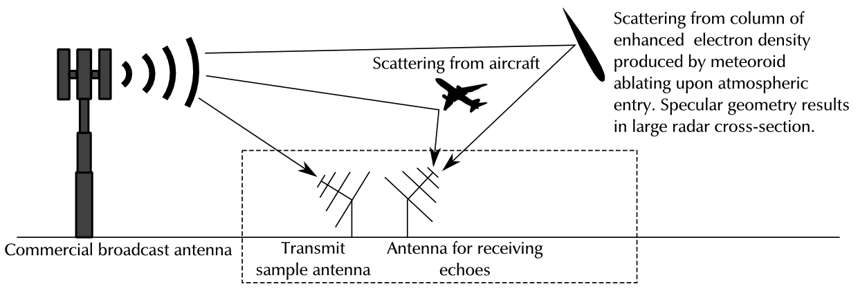
A passive radar is a special type of radar doesn’t require you to have a transmitter. You rely on a radio transmitter of opportunity provided by somebody else to illuminate radar targets. This can be your local radio or television station broadcasting with up to several megawatts of power. The advantages compared with a normal radar are numerous:
- You don’t need a transmitter, which is a good thing because high power radio transmitters are large, expensive, power hungry, and contain dangerous parts..
- Being a pirate radar operator can sound exciting, but you really don’t want to transmit without an FCC license. Passive radar allows you to operate a radar with kilowatt or even megawatt class effective radiated power, without braking any laws or regulations.
- A passive radar system is inherently multi-static. A single station can multiple transmitters that can be in different locations. This allows the three dimensional trajectories of radar targets to be estimated. There are many radar targets that have illumination and viewing angle sensitive radar cross-sections. A good example is a specular meteor trail echo, which only has significant radar cross-section only when the illumination angle viewing angle combination is a specular reflection. With a multi-static system there is a greater chance that such a radar target is seen, as there are multiple different simultaneous illumination directions occurring at any given time.
- There are many radio transmitters out there: Television, FM radio, and AM radio are the most obvious ones, but cell phone towers and even satellites can be used for passive radar. These transmitters cover a wide range of frequencies, which is really useful for radio remote sensing, as radio propagation characteristics and scattering properties of different media and radar targets can be highly frequency dependent. For example, if a radar target doesn’t have a large enough radar cross-section on one frequency, there is a good chance that another frequency will work better.
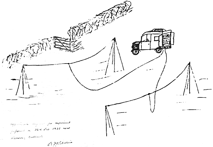
While most radars systems we know nowadays have a dedicated transmitter, the idea of passive radar goes way back. One of the first radar experiments could be classified as a passive radar. In 1935, Sir Robert Watson-Watt and his colleague Arnold Wilkins performed the first aircraft tracking radar experiment by detecting echoes from a Heyford bomber aircraft illuminated by a BBC shortwave wave radio transmission. The figure on the right shows the two dipole antennas and the mobile laboratory used to perform the measurement. This seminal work was the basis of the Chain Home early warning radar system that went on to save numerous lives during the Second World War.
There are a large number of non-military applications for passive radars. I’m interested in the use of passive radar for geophysical and astronomical radio remote sensing. An example of a successful passive radar system used for geophysical remote sensing is the Manastash Ridge Passive Radar developed at the University of Washington, which was used to study ionospheric irregularities produced during geomagnetic storms. In the last 15 years the technology has become much more accessible, making it possible to perform these types of measurements with easily obtainable hardware.
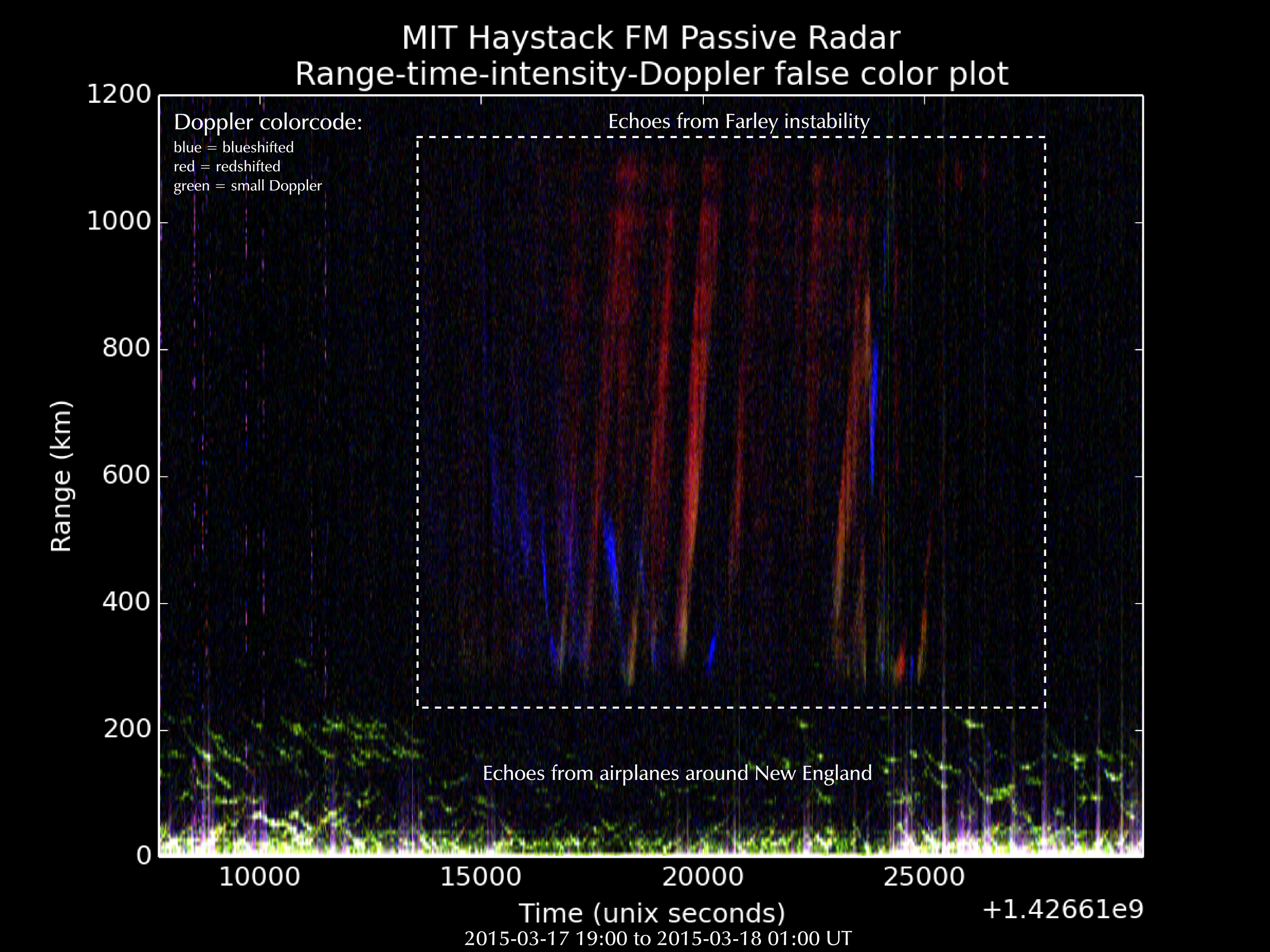
The Manastash Ridge radar used FM radio for passive radar, which is probably the easiest to start with, because the bandwidths of individual stations are relatively modest. With FM radio, you can also typically observe not only ionospheric irregularities, but also meteor trails and movements of airplanes flying within a 100-600 km radius of yourself. A recent measurement that I performed during a geomagnetic storm is shown in the figure below. You can see large scale ionospheric irregularity structures that are moving across the field of view at 1000 meters per second associated with the aurora borealis north of the passive radar receiver.
The thing is, pretty much anyone can do these types of measurements themselves. That is if there was open source software to analyze the data. This would open the door for citizen scientists interested in a broad range of topics:
- Meteor surveys of meteor radiants. The CMOR radar found 12 new meteor showers just by looking at meteor radiants. While this was an active radar, the same could be done with a digital TV passive radar system. Radar allows you to observe a lot more meteors than you can optically.
- Mapping the locations of aurora borealis and the presence of strong ionospheric electric fields by observing echoes from ionospheric irregularities. This tell us about the interaction between the Solar wind and the plasma surrounding our planet.
- Measurements of atmospheric winds using Doppler measurements of meteor trail echoes. These are good tracers of the neutral wind at altitudes between 90 and 110 km.
If there were a network of passive radars around the world, there would be a great potential for new scientific discoveries to be made.
Example hardware
A surprisingly small amount of hardware is needed to build a simple passive radar:
- Personal computer (a dual core newer than five years old will do).
- Dual channel software defined radio.
- Two antennas.
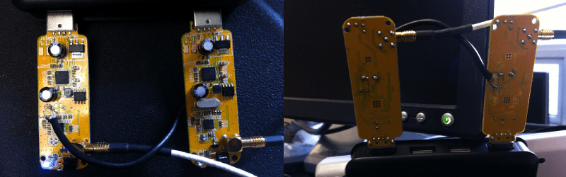
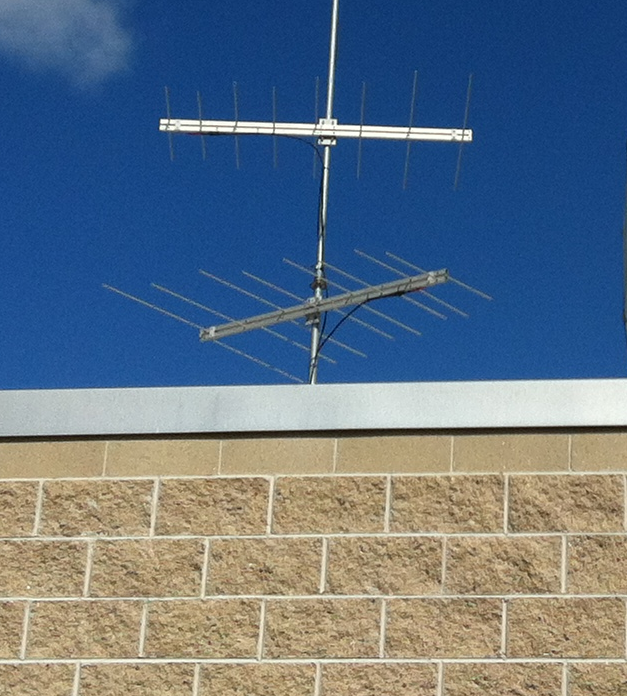
An example of a receiver antenna pair used for FM radio passive radar is shown below. Both antennas are log-periodic antennas that are broad band in nature, but also have some degree of directionality. One of the antennas is pointing towards the FM radio transmitter and used to obtain a measurement of the waveform transmitted by the radar. The other is pointing towards the opposite direction and is used to measure echoes. All of the example measurements shown in this article were performed with these antennas.
The signals from these two antennas need to be recorded in a coherent manner. This means that we need two channels with samples that are aligned. This is typically achieved by using a common clock used as a reference for the downconversion stages and the analog to digital converters. The picture below shows two possible off-the-shelf devices that can be used for passive radar. On the left is a modifed dual RTLSDR R820T dongle system I hacked together for $16! On the right is a USRP N200 software defined radio with a dual channel TVRX2 tuner daughter board. A word of warning before rushing to implement the RTLSDR approach: there are subtle tweaks that need to be done in order to make everything work, involving aligning samples and aligning the center frequencies of the two data streams. The limited dynamic range also makes it much more difficult to get good measurements out of the system as the levels need to be carefully adjusted to get enough signal into the receiver while avoiding compression or clipping of the signal. But it can be done if you have enough patience! I’ll try to share what these tweaks are in the next post.
In order to get more fidelity out of a passive radar system, it is advisable to have a preamplifier and band-pass filter between the antenna and the software defined radio to reduce out of band noise contaminating the measurements and to increase signal levels so that they are more suitable for the digital receiver.


Signal Processing
In order to obtain passive radar echoes, we need to apply some signal processing magic to the digital signals recorded by the hardware. We first need to get rid of the strong direct path signal so that we can observe the weaker echoes. Robert Watson-Watt and Arnold Wilkins simply used an opposite phase signal to cancel out the direct path signal in their early Daventry experiment. Modern signal processing can do this much better, not just removing the direct path signal from the transmitter, but also reflections from mountain sides and other large scatterers that might mask weaker signals of interest. This is done by using a well known statistical signal processing technique called linear least-squares estimation to deconvolve the phase and amplitude of the direct path signal and the echoes from mountains and other strong non-moving scatterers (also called radar clutter).
After the strong direct path signal and clutter has been estimated, it can be subtracted from the measured signal and the signal processing to estimate the weaker echoes from airplanes or meteors can be performed. Because we know that the weaker targets that we are interested in have a significant Doppler shift and Doppler spread, we can’t make the same non-moving target assumption we did for the clutter. However, we can still make the assumption that the target has a scattering Doppler spectrum that doesn’t change over a long enough period of time to allow us to estimate the range-Doppler spectrum. This allows us to perform deconvolution on the autocorrelation function of the received echo. This is something that is called lag-profile inversion. While this sounds complicated, it really isn’t.
Once all of this is done, we can plot the results. If you see airplanes, your radar is working. While airplanes are boring radar observables, they are by far the easiest ones to see and they are there all of the time. Meteors are more transient, but also should be relatively easy to measure if you know what to look for. They appear as quick blips at near zero Doppler shifts.
Angle of arrival
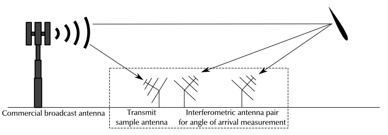
There are also many different variations of FM radio passive radar that can be done. For example, by adding a third antenna to the system, one can perform angle of arrival direction finding by inspecting the phase difference (time of arrival) between two receiver antennas spaced apart from each other. The video below shows phase difference measured using two different receiver antennas. In this video, the phase difference between the two antennas is used to select the color of the pixel (hue) and the echo strength is used to color code the brightness of the pixel. Again, lots of airplanes and specular meteor echoes can be seen.
That’s all for this post. In upcoming posts I’ll go into more detail on how passive radar works in practice.
 I’m a radio science geek who loves working with radars and other remote sensing techniques. I’ve programmed computers and dabbled with electronics ever since I was a kid. I really got into designing and building radio remote sensing instruments while working on my doctorate titled: “On Statistical Theory of Radar Measurements” (find a link to it on my webpage). I wasn’t happy with just writing measurement equations, I wanted to try things out in practice. Currently I work at the MIT Haystack Observatory, where I explore a number of exciting topics, including, but not limited to: high power large aperture radar measurements of the ionosphere, meteors, and planetary objects; passive radar, milliwatt class spread spectrum HF radar, megawatt class ionospheric heating, ionospheric remote sensing with global navigation satellites, and radio astronomy. I’ve published two open source projects that turn your software defined radar into a radio remote sensing instrument: the GNU Chirp Sounder, which allows you to listen to over the horizon radars and chirp ionosondes all around the world; and the GNU Ionospheric Tomography Receiver (Jitter), which allows you the determine the line integral of ionospheric electron density by listening to 150/400 MHz coherent beacons on satellites.


This is good stuff!
I hope that soon these ideas might be applied to contribute to the search for earth-crossing asteroids.
This reminded me why I read posts on hackaday. More of this please.
Shameless, shameless plug: You might want to read the GNU Radio guided tutorials, https://gnuradio.org/redmine/projects/gnuradio/wiki/Guided_Tutorials . They explain how you can develop complex SDR applications in no time :)
I must agree, Juha, that was impressive documentational and development work!
Don’t worry, I’ll get into the gnuradio stuff next.
Not worried the least :) More totally impressed.
This is great stuff. I’m looking forward to reading the followup articles.
Thanks! Looping forward to learning more !
This is awesome!!! I need to get another SDR
great writeup, good stuff.
So glad to be reading this! The doing this in realtime 3D has on-and-off puzzled me for a few years now and has helped me learn a LOT of mathematics. e.g. with just two more receivers you could arrange your antenna in a tetrahedron – a simplex of 3-space – so you should be able to recover signal positions if you know the speed of light and you have an accurate clock in your line of sight; such as a hydrogen frequency standard broadcasting a time signal around 60 kHz. =)
Apparently all the hooplah about Perleman sums up to complete understanding of 3-space, so there is no theoretical reason why it can’t be done. From the practical side, CT scanners – that HaD is already familiar with – have lead to really efficient numeric techniques, so it should not even be computationally infeasible to do this. Refer to http://en.wikipedia.org/wiki/Hough_transform#3-D_Kernel-based_Hough_transform_for_plane_detection_.283DKHT.29
I wouldn’t know what to do with this tech even if I somehow managed to understand all the math, build a huff-puff upconverter for a time standard, and implement it in OpenCL/GL… I’d probably turn it into a VR art project for people to ooh and aah at. :p
Still, good exercise for the grey matter to think about this stuff, and I’ll be eagerly awaiting the next installment! =D
isn’t the hydrogen line somewhere around 1420 MHz ?
Radio clocks transmit at much lower frequencies:
http://en.wikipedia.org/wiki/Radio_clock
Come to think of it, I could just look up how they build those things to learn how to propagate good signal qualities.
Nice soldering!
If you used an FM stereo broadcast then could you band pass the 19 KHz stereo pilot tone to get a much cleaner reference signal? Would that help when the audio goes silent? I’d think it would also help with the Doppler shift as well.
Continuing with the 19 KHz pilot…not sure if the following is correct.
Each antenna could be setup with a PLL that would share the same 19 KHz reference clock. Then you could feed the output of both PLL’s into a third PLL to get phase angle measurements.
The continuous wave pilot of a distant transmitter cannot be used as a clock or PLL sync for stabilizing a local timebase. Available as a stand-alone device, the popular GPS 1 second tick, is used to stabilize local oscillator clocks. A PLL is synced to the tick to force the local oscillator from drifting. Since there is no synchronization pulse from the Stereo Pilot, is is not usable as a clock. Clocks must be local things; the farther away the timebase is from the source of the clock, the more error, drift, or phase noise is possible. The possibility of using the GPS tick for long baseline interferometry is done in Radio Astronomy, but only with great care (expense), and a several very good Hydrogen Maser Clocks, certainly not in real time.
If you do not know how PLLs work, very simply, they are complex non-linear circuits comprising a low pass filter, a 2 input comparator, one or more programmable counters, and a Voltage Controlled/Numerically Controlled Oscillator. To forgo a tedious circuit description, the 1PPS from the GPS constellation is used to check the numerical accuracy of the Master PLL Counter timebase once per second. If the count is too high or low, the Counter is programmed to adjust the frequency/phase of the oscillator, reducing the oscillator’s drift (but not perfectly). Multiple Oscillators of different frequencies can be synched to the 1PPS at the same time by sharing the local Oscillator in a Master SDR. This is how SDR (RADAR and Radio Astronomy) works to sync to multiple timebases employing many receivers and/or transmitters. What is not usually mentioned is that these SDRs are physically close together. This is why it takes a FPGA-controlled timebase in every unit to keep multiple timebases phase locked together on a single 1PPS, a Command and Control nightmare otherwise.
Problem is that with the pilot alone, you just get a continuous sine — that’s great to estimate doppler against, but not so much for range. In fact, your resolution gets better with higher bandwidth. Think of it like this: Juha’s algorithm is able to match received energy to a spot in the range/velocity plane. The more energy that algorithm is able to observe, the less random (due to noise) the estimate is.
It doesn’t really matter that the RTL sample clock is crap because both channels are downconverted and samples with the same clock. The relative phase difference between channels is very small.
Norwegian black metal, which is essentially white noise, would be the best audio playing on an FM radio station. An even better radar waveform is anything digital, as it typically has a flat spectral shape across the band it occupies. This is to optimally get bits across the medium, which is a similar objective as minimizing the variance of radar target estimation.
In the above video, the point-like targets spread in range when there is a pause in music and the frequency modulated audio essentially becomes an unmodulated carrier. This screws up the range ambiguity, because a carrier wave (essentially a constant in baseband) has a flat autocorrelation function. White noise (black metal) on the other hand has a very sharply peaked autocorrelation function.
Psst. https://github.com/steve-m/kalibrate-rtl
I successfully tied 2 Dongles together, one clock driving the other after carefully removing its crystal. The trick to a stable and reliable sharing of clocks from one dongle to the other is to add a very small RF capacitor to the source dongle’s crystal output to capacitively couple its output to the crystal input of the other dongle. The capacitor transfers the clock signal without loading the source oscillator. However, it is very important to select the appropriate value of coupling capacitor, too large, will load the oscillator, too small the signal integrity to the slave tuner is to low.
The capacitor is seen on the right dongle under the coax on the right crystal pin, on the left dongle the coax is connected to the left crystal pin (after the crystal is removed). The choice of coax is also important, Teflon low C is the one to use. Stray capacitance from the wrong coax causes phase instability. Sub-picofarad stray capacitance causes phase shift. Also, the dongles should be close but not too close, and physically parallel, not opposite each other. The source clock coax should be grounded close to the crystal, both ends of the coax are grounded, do not leave the sink dongle’s coax shield floating. For a photo…
http://www.salsburg.com/radar/uploads/IMG_5234.jpg
http://radar.salsburg.com/index.php?p=/discussion/4/software-defined-radio
On using Standard FM Radio broadcast transmissions. In the USA, most major cities have at least one Station broadcasting Digital HD FM. This source of constant modulation energy seems to be overlooked for Passive RADAR. These Digital transmissions seem to be ideal for overcoming Range Ambiguity difficulties. Each transmitter is broadcasting 2, 100 KHz wide Digital signals whose amplitude does not vary and are full of multiple constant carriers and very dense modulation. Listening to them with an “Analog” superhet receiver they sound like white noise. Examining them closely with FFT, they appear well suited for Ranging, perhaps with an accuracy of 1500 meters.
Thanks for the useful info. I’m glad you got this working.
I’ve also thought about using the digital fm transmissions. I haven’t tried them yet, because they have less transmit power than analog fm, but the waveform would be better.
How much capacitance would be appropriate?
And that is why the Manastash Ridge Radar uses KISW 99.9 (Seattle rock station) as the active transmitter. Now I chuckle just about every time I turn on the radio. (Little do those metal heads know they are contributing to science…mu ha ha ha)
I must point out that the Manastash Ridge Radar is more Forward-Scatter RADAR than Passive (Bistatic) RADAR, even though they post process the recorded files for Doppler/Range calculation. This RADAR is a very special case (expensive) based on special local conditions, where the Reference/Surveillance Receivers are separated by mountains making the products of the receivers virtually over the horizon from each other.
Just a question, if a stealth plane passed between the backscater from the meteor shower ionization and the receiver wouldn’t it show up as a “hole” in the returned signal?
Not on VHF. Most “stealth” stuf is aimed against microwave radar. Old VHF radas see them just fine.
Made me want to dust off my sdr again!
Juha,
Would it be possible to use two HackRFs, since they have a clock-in/clock-out for synchronization?
Yes, this is an excellent application for HackRF clock synchronization. It’s very cool that it can also be done with hacked TV tuners.
I didn’t know hackrf had that feature. You should be able to do all of this with two hackrfs if you can synchronize their clocks. I don’t have even one, so I can’t try it myself.
I’ll send you my hakrf one if you can scrounge another one for experimentation. I don’t have the time or skill to do justice to the hardware, would be nice to see it used for something really intersting.
I’d be happy to send you one as well Juha, as I have a couple of them.
Jeff
Thanks for the generous offer Jeff and Robert. I’ll first try to see if I can borrow a few from some friends. I’ll get back to you if I’m in a “desparate” need for one.
This is awesome! I’ll definitely be trying this one out when I get the time.
Great post and a good research direction! This work is something that is worth spending time and incorporating in any atmospheric sensing activities. I am wondering through, how any dielectrification (electric convergence, as defined by Heaviside) is detected by the measurements. Expecting your next post!
Have you tried this yet 😉
I’m just thinking out loud here, to see if what I think I understand is in any way right ?
speed of light in a vacuum c = 299792458 m/s
refractive index of air is about 1.0003
speed of light in air is about 299700000 m/s
sample rate of RTL-SDR is 2.4MHz (without samples being dropped)
Is the distance resolution 1 sample ? (417ns or ~125 meters) ?
Almost. The signal travels to the target and back. Because this is almost a monostatic radar, the range resolution is about 1.5 km. The equation is \delta r = c/(2b). I’m using b = 100 kHz bandwidth. This is mostly limited by the transmit bandwidth of the FM radio station is approximately 100 kHz.
With digital TV you can get better range resolution because the transmit bandwidth is much higher, 62.5 meters with the maximum 2.4 MHz bandwidth of the rtl dongle.
OK so everything is happening in the frequency domain, and you are looking for Doppler shifts (which means that objects must be moving to be detected). The phase offset gives you the distance and the Doppler shift gives you the speed.
So are you decimating the 2.4MSPS down to 100kSPS for an extra 13.5dB (6dB is 1 bit, so 2.25 extra bits, 10.25 bits in total ) of dynamic range ?
Digital TV signal is nice for range resolution but its ambiguity function is not that brilliant. Most of the time, the DTV is is a single frequency network which makes quite challenging to “untangle” a true position of a target in a muti-static configuration. As for a PCL system that explores FM transmitter: the direct signal coming from the transmitter to the reference channel is also illuminating the measurement channel (assuming that the reference receiver is collocated with the measurement channel(s)) causes masking of weak echoes (we use an adaptive filter to remove the strong reference signal for the measurement signal. Why an adaptive filter? Because the whole environment is a time-varying system).
To get a decent detection range you need ADC converter with enough dynamic range. I have observed that the phase noise of the local VCO plays also an important role in the system’s performance. (http://en.wikipedia.org/wiki/Passive_radar).
Well done and have fun.
Cheers,
Darek
What do you mean by “Digital TV signal is nice for range resolution but its ambiguity function is not that brilliant”? Is the range ambiguity very elongated perhaps in Doppler direction? I’ve never really played with DTV, but I am planning to do so in the future. I don’t mind the lack of multi-static receiver-transmitter pairs. For meteor trails, interferometry for angle of arrival is needed due to very aspect sensitive radar cross-section.
I have heard that phase noise and ADC dynamic range is an important factor for PCL. I have a feeling that they are not as limiting as people think. With less dynamic range, you need to be more careful not to compress or clip anything. Things like proper DC offset removal are important, especially for the RTL dongle. To my great surprise, I was able to get essentially the same performance with an 8-bit ADC and a $8 dongle as I got with a 14-bit ADC and a much better clock.
You get a lot of processing gain through digital filtering and decoding of the echoes. I’ve explored the phase noise issue with equations and any way that I write them, the phase noise terms aren’t that bad as long as both channels share the same realization of phase noise. If it is cross-channel phase noise (e.g., two independent crystals with different close-in phase noise), then I see how it can be a problem.
Is there any publication that you can point me to that discusses the inherent limitations to passive radar caused by phase noise or ADC dynamic range for passive radar performance? I’d love to take a look at some equations to see what I failed to include in my equations.
I use something equivalent to the adaptive filter. Instead of determining a filter that minimizes clutter and direct path signal in the measurement channel, I deconvolve with direct matrix equations an extended target with a 1 second coherence. This means that every second, I get a different estimate of the direct path and the clutter environment, which I then subtract from the measurement channel.
FM radio based bistatic radar – IEEExplore
Advanced Radar Techniques And Systems – Peter Peregrinus Ltd., The Institution of Electrical Engineers, ISBN 0 86341 172 X
Principles of Modern Radar, Vol. II: Advanced Techniques – SciTech, ISBN 978-1-891121-53-1 (hardback), ISBN 978-1-61353-024-5 (PDF)
Please, if you mean passive coherent location do not use the acronym PCL, it is confusing as most acronyms are.
Jan,
The discussion on naming has started some time ago. Finally, the terms PBR (Passive Bistatic Radar) and PR (passive radar) have been accepted [1]. I am still using the old acronym from time to time :)
1. N.J. Willis, H.D. Griffiths. “Advances in Bistatic Radar”, SciTech, 2007.
Excellent! Looking forward to your next post.
Really great topic, and reading as well! After a successful implementation of the GNU Chirp Sounder I look forward to the upcoming posts for this project.
I’m glad to hear you got the chirp sounder working!
Great!
The superbly excellent BBC series ‘The Secret War’ made back in 1977 covered the Watson-Watt detection experiment and even recreated it with one of the original researchers taking part. Here it is in the second episode ‘To See for a Hundred Miles’, starting around 9:20 in https://www.youtube.com/watch?v=ZPwDicTQVBo
That is awesome. I had never seen this before. Arnold Wilkins redoing the classic experiment!
Any chance to see second part of this? Too tired to constantly refresh this page waiting for the new part..
I’m working on it. My estimate is that in about two weeks I’ll post the second part. Vacation and travel sometimes gets in the way of doing truly fun stuff. Thanks for the interest.
Thanks for taking the time to share this.
Any news so far? :)
Was the second part posted? I can’t find it.
Hi
A long time ago I used a ‘forward scatter’ method to detect meteors. I listened to a video carrier of a TV signal of some Russian TV station at about 49.7 MHz. The Doppler effects due to high winds in the upper atmosphere were clearly visible in the audio spectrum.
I have a couple of questions:
1) Suppose the *direct* signal of the transmitter is not detectable. Does the system described by Juha work anyway ?
I think I cannot get the distance of the object in this case.
2) Suppose I want to detect meteors anywhere on the sky, so I need an antenna with (almost) isotropic beam, not a directional antenna.
Is this feasible, or do I need a huge number of (isotropic) antennas to have enough collecting area ? On the other hand, I am
interested to find out the position of the meteor on the sky (interferometry), so I do need several antennas anyway.
Of course the feasibility depends on the power of the transmitter…
3) How about using military radars as transmitters ? There is Lekhtusi radar station in Russia, close to the border of Finland and pointing towards Finland. Do you know the frequency and power of these stations ?
cheers, Kimmo
2) Directional antennae are required for reception. Computing Doppler and Range are based on several things; most importantly the bandwidth and complexity of the transmitted energy, the wider and more complex the better. Meteors scatter degrades as frequency increases. Meteor scatter is an atmospheric phenomena best at around 30 MHz. However RADAR is best at frequencies several octaves above this. Digital TV signals are powerful enough to receive meteor scatter. More receiving antennae translates into more receivers and exponentially more computation. Three dimensional imaging is possible with an array of at least 4 antennae from 2 transmitters, but this is not for the Amateur; the number of receivers and the size and number of files is massive. Supercomputer computation speeds are needed, never mind the real estate for the antennae. Someone needs to experiment with GPU Computation. Real time computation and display of Passive RADAR is a problem of money, the computers and receivers needed to do the computation will not be cheap. Algorithms are needed and do not yet seem to be available to post process the recorded files to zero in and process only the signals of interest so the computations will not be so intensive. Processing the entire recording session is time consuming, not real time.
3) Using military RADAR signals in a Passive RADAR application is possible but not practical. Air Traffic and Weather RADAR signals are too high in frequency, and are too periodic to be reliable for Passive RADAR Meteor detection, that is unless you are the operator of the RADAR Set. The Lekhtusi RADARr may be used for Forward Scatter RADAR. Its frequency probably is low enough to reflect from Meteor trails at great distances. However, the RADAR is probably modulated to make it more effective which offers detection problems for Meteor Scatter.
I will attempt to answer your questions…
1) Passive RADAR, needs One antennae and one receiver in direct line of sight to the transmitter. The cleaner the signal image from the transmitter the better; the lowest amount of multi-path and ground reflections. Some multi-path can be filtered if is constant and fixed like that of a mountain or building. Distance technically labeled “Range” is a computation applied to the signals from at least 2 receiving antennae and 2 receivers, based on the distance to the transmitter, to compute the distance to the object of interest. See my Forum. radar.salsburg.com
Jay, sorry for my off-topic reply here. Earlier in the comments you mentioned that the Manastash Ridge Radar was primarily a forward scatter system. Although it does collect forward scatter, it was designed to be quasi-backscatter. The weak signal receiver is about 100 km from the transmitter, but the intended target (auroral scatter) is located 350–1150 km to the northeast. So, even though the baseline is large, it’s still quasi-backscatter in its intended operation.
We’ve also realized that passive radars can tolerate non-syncronized clocks, as long as the clocks are close in frequency and stable. This is because you can numerically synchronize the data by looking for ground clutter, and removing any remnant Doppler shift. We successfully recovered a Seattle–Spokane data set in 2002 or so when the Spokane GPS receiver failed … it’s handy to have GPS, but not necessary.
What this means is that we could probably replace all the MRR receivers with a couple USRPs and have it work as well as the earlier equipment.
John Sahr, UW/Manastash Ridge Radar.
may I get modeling/simulation of passive bistatic radar, in MATLAB, kindly help me.
thank you,
Could you make a guide for own self made passive radar from this article for the radar tutorial? (http://www.radartutorial.eu)
Really bummed that the author did not follow through and post the other parts to this write-up. Please re-consider! This is a really interesting topic.
Me too I read this thinking the DSP code would be posted and explained :/
Eagerly awaiting the Python code and decription of required level tweaks etc!
Really interesting. I imagine that Juha is busy with his research, but this is really enticing. I too hope he finds time (and I know this is time consuming) to add more material.
Great excelent stuff for passive radar project, i hope that Juha will have time to sharing another part of his research. Still waiting for update .
Perhaps the most robust signal of a local Continuously Operating Reference Station (CORS) that is part of a network of real-time kinematic (RTK) positioning base stations, broadcasting global navigation satellite system (GNSS) corrections, would be a good candidate for the baseline transmission as it also provides a standard time reference.
great job!!!
As a HAM, I find this very interesting. Knowing if and when meteor scatter happens to aid in transmitting distances would be a welcome addition to my ham shack.
Hi I’ve been thinking for a longtime that a simple DF system for K Band Radars would be of great help to sailing vessels avoid collisions. While Radar is great at this it draws a LOT of power as such most small sailboats don’t have them and even larger sailboats don’t use them while underway do to their power budget. Does anyone know if this has been done as a DIY? Thanks
Hi Juha.. you said that in later posting will go through more detailed block diagrams of the different parts of a passive radar system, provide example data, and give some Python scripts that can be used to perform passive radar signal processing.. still waiting the postings..
nice work,
but I didn’t see the python script? is it public or private?
thanks
Hello,
As analogue signal broadcastings are closing down from all over the globe… I found no valid channel in my vicinity in this part of the globe for studying forward scattering of radio waves by meteor. I am very much interest to establish a set up like yours. I will be obliged if you kindly help me technically in this regard. Thanks for your kind cooperation.
ITAR may apply if your passive radar uses more than 125kHz of bandwidth ( https://twitter.com/vk5qi/status/1591628725141270528 )
KrakenSDR just took all their open source passive radar software and documentation offline, while they seek legal advise.
I found this article interesting and reminded me of a project we were working on at Collins Radio in the 70s. I was a communications programmer and the project being considered would be used to bounce radio communications off comet/meteor tails after a nuclear war. I never personally worked on this but the concept was seriously considered. From your article it would appear systems could be developed that would allow ships to use over the horizon foreign radar signals to passively detect and track assets without using active radar, virtually making the user invisible. They may have this now but I know this would not have been possible too many years ago.
Tropospheric Scatter has been used for decades for short burst over the horizon communication.
Really like this article – very good stuff. I have a quick question: I am trying to create a passive bistatic or multi-static radar by listening for the echos from Primary Surveillance Radar, but not sure what sort of antenna I would use (capable of receiving 2.7Ghz-2.9Ghz). Any idea where I might find such an antenna of the right size? Are there other antennas that might also work for this purpose. Thx.
Might want to try a Helical antenna.
Ray
Mitch Randall wants to use a low cost citizen US wide passive radar network for ufo/uap tracking, in order to speed up disclosure. https://youtu.be/jPffL1YFtrU?si=9Ufr9waMBYJdp3L8
Looking for someone to build system to watch the planes flying around my home with no transponders on