Every now and then a remote control acts up. Maybe you are trying to change the channel on your television and it’s just not working. A quick way to determine if the remote control is still working is by using a cell phone camera to try to see if the IR LED is still lighting up. That can work sometimes but not always. [Rui] had this problem and he decided to build his own circuit to make it easier to tell if a remote control was having problems.
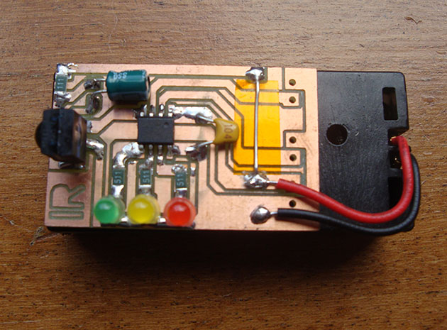
The circuit uses a Vishay V34836 infrared receiver to pick up the invisible signals that are sent from a remote control. A Microchip 12F683 processes the data and has two main output modes. If the remote control is receiving data continuously, then a green LED lights up to indicate that the remote is functioning properly. If some data is received but not in a continuous stream, then a yellow LED lights up instead. This indicates that the batteries on the remote need to be replaced.
The circuit also includes a red LED as a power indicator as well as RS232 output of the actual received data. The PCB was cut using a milling machine. It’s glued to the top of a dual AAA battery holder, which provides plenty of current to run the circuit.


Simpler yet. look at the remote via the camera on your ‘phone!
Did you read the first paragraph…?
+1
This was already addressed
I’d be interested to know in what situation does the phone camera trick not work? It should even work for IR leds with different wavelength and modulation frequency, unlike this device.
It doesn’t work if your phone has an IR filter (mine does).
Looking directly at the remote will work even with an IR filter. Have never seen a case where the phone would see something but the remote still not function…
Looking at the schematic, pin 8 of the microcontroller should connect to ground.
It is connected on the PCB.
Pin 8 is connected to ground in the picture.
?
It is connected on the PCB, he soldered it on the side. Same trace as the cap and black wire.
Looks like a good build. I don’t know if I would get that much use from it unless I was doing projects that used remotes. But, A nice skill building project nonetheless.
Does anybody know what CAD program can make traces like that? Or, at least, how this technique is called? I mean making traces as big as they can go should simplify etching too. Yes, you do lose the ground plane but still.
Look for Isolation Milling. Here’s one program I’ve used successfully in the past
http://ofitselfso.com/LineGrinder/LineGrinder.php
As far as I can tell, that program just generates GCode based on already existing Gerbers. I was talking about the way the PCB just has common “fields” or “zones” instead of the traditional standard size pad and standard width track between pads with a ground plane surrounding everything else. Can you do that in KiCad, or in Eagle perhaps?
There is no option to do it in kicad or eagle, unless I’ve missed it. I’d imagine you could work from a schematic directly to a board quite easily for simple circuits like this. A good workflow might be, design schematic in EDA tools, place components in desired locations in EDA tools, export and perform routing in a graphical tool, inkscape or illustrator? Would be tough if you decide to move a component after you had started routing..
I made a simpler tester a while ago for a shop. It was without any micro: just a bunch of 3 pin sensors which include the demodulators and LEDs. I remember needing more sensors because of the different modulation frequencies (36, 38, 56 KHz?)
I added a LED to my original Xbox remote receiver as it was having some issues receiving. Always thought it was not getting strong enough signal. I finally sat down and decoded the signals with a logic analyzer to program my “JP1” universal remote. It turns out that their mark/space encoding didn’t allow for slow rise time (open drain?) of the receiver. So after tweaking the IR mark and space from the IR encoding, the issue was gone.
Even simpler, connect the data out to an LED and skip the chip. you can easily see the continual stream or that it stops.
I built one many years back using the IR receiver salvaged from a dead VCR and one of those (then) new-fangled blue LEDS. You would see the LED light up (and flicker) when active.
Back in the old days (1980s) we had to buy a plastic card that had a small patch of orange on it. Exposing the patch to fluorescent light for a while to charge it up and then pointing the IRLED to the patch supposedly caused the orange patch to glow. I’m not sure if I ever got mine working. By then I found out video cameras such as those used with the new-fangled VCRs could show the LED flashing.
I still have one of those cards, a buck or two from radioshack if memory serves.
The thing pretty much worked as advertized, if not ideally.
You let it absorb light similar to what one would do with glow-in-the-dark plastics and such, only the orange strip doesn’t fluoresce until strick by IR light.
The glow was very similar to shining focused direct light (IE a pen light) onto a glow in the dark plastics.
The IR source needed to be fairly bright to cause the reaction, and it was hard to see outside of a dark room.
I only found it useful to determine of the IR source was even outputting light at all or not. All too often it was, just not enough to trigger the receiver at distance, or was sending bad/garbled data – neither of which the strip could differentiate.
Perhaps a few alphanumeric LEDs to actually display the number sent by the remote might be helpful?
AM portable radio. They “tick” or buzz when keyed and held close to the ferrite antenna. You can hear the pulse train.
Ditto.
You can buy/make a IR photodiode -> BNC adapter to use with scope/LA for a few dollars. Doesn’t require a code/micro and no analysis hassle.
you can also point the remote at the eyeball for the garage opener. it will make the LED blink
The Infrared detective featured a couple of years ago was also neat, with the added benefit of seeing the transmitted code:
https://hackaday.com/2018/04/27/ir-detective-eases-development-with-compact-decoding/