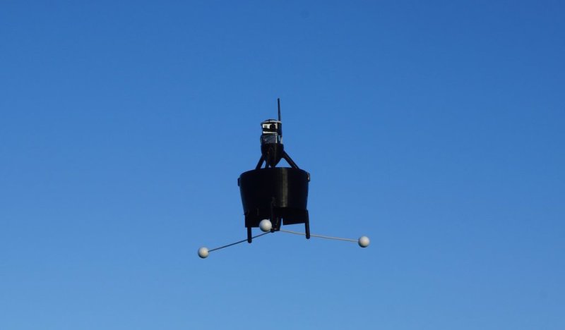
A while back, we wrote about the ducted fan, single rotor, VTOL drone that [Armin Strobel] was working on. It wasn’t quite finished then, and hadn’t got off the ground yet. He’s posted an update, and from the looks of it, he’s made tons of progress, including a first flight with successful take-off and landing.
The successful flight was no coincidence. Tuning any kind of ‘copter is a tricky business. Handling them manually during testing could be outright dangerous. So he built two different test-beds from pieces of wood, some 3D printed parts and bearings. One lets him mount the drone and tune its pitch (and roll), while the other lets him tune the yaw parameters. And just like they do in wind tunnel testing, he fixed short pieces of yarn at various points on the air frame to check for turbulence. Doing this also gave him some insight into how he could improve the 3D printed air-frame in the next iteration. He repeated the tests on the two test beds, going back and forth to make sure the tuning parameters were not interfering with each other. He also modified the landing gear to improve stability during take-off and landing and to prevent tipping. [Armin] is using the PixHawk PX4 for flight control and a BeagleBone Black for higher level functions and control.
Once the first flight showed that the drone could do stable flight, he attached a Go-Pro and recorded some nice video on subsequent flights. The next steps are to fine tune the flight control parameters to ensure stable hovering with position hold and way point following. He may also 3D print an improved air-frame. For details about the build, check out our earlier blog post on the Ducted Fan Drone. Check out the two videos below – one showing the first flight of the Drone, and the other one about the test beds being used for tuning.


First flights don’t come much better than that. It just shows what a bit of preparation (tethered tuning) can do. Brilliant!
That’s awesome, also it reminds me of a flying basket. Good job on the tuning.
Incredible work! I was expecting two contrarotating propellers, but no, only one. How the contrarotating force is compensated? Trough controlled fins in the base?
Thrust vectoring commonly uses gimballed nozzles these days, but fins or vanes work fine too, such as the thrust fins you can see below the fan blades in the video, which can “contrarotate” and steer as well.
Vectored thrust can be used on planes too:
https://www.youtube.com/watch?v=6YkkZw9GVaU
The contra rotating force are mainly compensated by the asymmetric stators. They are shaped like an air foil to take the rotation out of the air stream. The fins are to control the direction of the air stream or add some rotation into it (which is used to rotate the vehicle around the vertical axis).
Nice design.
Now add some blinkenlights and fly it at night to troll people who believe in UFOs
You don’t believe flying objects can be unidentified?
Language changes. See: PC, meme, hack. UFO now means aliens, even though strictly speaking it shouldn’t.
I know from an canceled project that making something fly with only one propeller is extremely difficult. Also I am impressed that the center of gravity seems to be oboe the propeller so I think it is even more unstable ? Awesome work !! To be honest I am a bit jealous I never made it that far, but just a bit ;)
No, the position of the propeller has not really an influence on the stability. The flying vehicle will always rotate around the CG (not 100% true, but close). The distance between the control surfaces and the CG defines how strong and in which direction the corrections are necessary. The vehicle is pretty much indifferent.
See the Wiki page about the “pendulum rocket fallacy” for more info.
Yep, I made exactly that mistake and had to learn it the hard way :D
What’s the advantages of this configuration? Better efficiency due to one propeller?
The efficiency depends on the area of the propellers: The larger the better.
I’ve been thinking about this a bit lately….
remember newton?
F=m.a
Now a = delta-V/sec, and we can move the “per sec” over to the “m”.
F = mass/sec * deltaV.
So to provide a lift of 10N, we need to provide say 1kg of air a 10m/s delta-V.
1kg of air is about 1m^3. At 10m/s you need a 0.1 m^2 area to sweep that 1m^3 in one second. Assuming (best case) that the air was immobile before it entered the ducted fan, you’re acellerating 1kg to 10m/s every second. 1/2 m v^2 = 0.5 . 1. 10^2 = 50J.
So the theoretical minimum power for this situation is 50W.
Now if we swap the numbers and take for example 10kg of air a 1m/s delta-V, you end up with 1/2 m v^2 = 1/2 * 10 *1^2 = 5J every second.
at 1m/s you need a 10m^2 prop-area to process 10kg of air every second.
Expand the prop to 10m^2, and you only need 5W!
Yep, so the bigger is the prop, the lower is the needed speed and the better is the efficiency.
One prop. permit larger area and better efficiency than 4 prop. right?
The difficult thing is to control the drone with only one prop..
The correct question is…. why didn’t he just create a tail sitter ? The ducted fan just reduces efficiency while marginally reducing the effect of wind and in horizontal flight it offers nothing.
You asking the right question. Regarding efficiency you are most likely right. It is not all about efficiency otherwise multi rotors would never exist.
Very interesting work! Would you happen to have code showing how you integrated the BBB and the PX4?