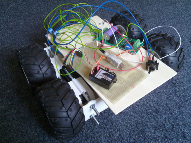
[Andrey Nechypurenko] has posted the second part of his robotics ground vehicle design guide. In his first post [Andrey] detailed the mechanical design decisions he faced. [Andrey] now begins covering the electrical components, starting with manual control using a standard radio control system. To accomplish this an RC system was used with an MD22 h-bridge driver and a picoUPS.
The MD22 is a neat motor control board which can take the PWM signals from the radio controller and use this to drive the DC motors. Optionally it can also use an I2C interface, giving a nice migration path to integrate with a microcontroller. Until that happens this can’t really be called a robot — its more of an RC vehicle. But the iterative design and build process he’s using is a good one!
The picoUPS provides on-board battery charging. Due to its UPS heritage it also allows the vehicle to be powered from an external supply, which has proved useful during development. Finally, a 5v regulator was required to supply the on-board digital logic. [Andrey] wanted a quick drop in solution with a budget large enough to allow for future expansion and went with the Pololu D15V35F5S3 which can supply 3.5 amps in a small and easy to use module.
After breadboarding the system [Andrey] fabricated a PCB to integrate all the components. The next step is to add sensors and and embedded computer to the platform.


I wonder how well you could daisy chain the Pico UPS.
It works quite well with lead battery. Very convenient during development where you can switch between wall adapter and battery instantly without restarting the system.
I think with my first reply I was too hurry did not really understand your question. But better later then never :-) . So the answer is – we did not try to daisy chain them. So I can not tell if and how it works.
Cool. Here’s an RC holonomic unit my son and I built: https://www.youtube.com/watch?v=LuMbSwsAkjQ
Has a Teensy for conversion of RC to motor drive, and plenty of room for upgrades.