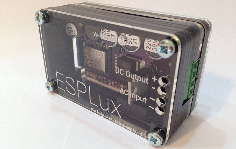
A common theme around Internet of Things things is connecting a relay to the web. It’s useful for everything from turning on a lamp from across the country to making sure your refrigerator is still running without the twice-hourly calls from the International Refrigeration Commission. For his Hackaday Prize project, [Matt] is turning lights on and off with an ESP8266 WiFi module, but not just any lights: he’s focusing on low-voltage lighting with the ESPLux.
Most downlights and landscape lights run off a 12 or 24 V transformer, and because [Matt] wanted to add dimming to his lighting box, he’s rectifying the low voltage AC to DC; PWMing an output to light an LED is a much better idea than chopping AC with a triac.
With a rectifier, MOSFET, and an ESP8266, the ESPLux is a simple build, but the project doesn’t end with electronics. for automation and control of these lights, [Matt] is turning to OpenHAB, automation software that works with everything you would ever use to make your home smart.


I wrote a series of articles on OpenHAB with step by step config instructions , as well as ESP8266 and Arduino sketches on http://openhardwarecoza.wordpress.com
Thanks Peter, this will be very useful for a project I am working on. Interesting seeing you here ;) btw, gonna be doing a speech in a few days at our school sciex expo on building 3D printers and the course we arranged using your printers, will be sure to give credit where due! :D
Nice work! I’m going to design a PWM LED strip driver with a microcontroller and mosfet. I need a fair amount of current for all of the LEDs, so I’ve been looking into cheap sources of high-current 12v. Switched-mode power supplies seem like the best(efficient and low cost) solution, and they don’t require an external rectifying circuit.
Thanks for the article Brian! I wasn’t expecting that. Haha. This is my first real electronics project. I have documented as much of my learning process as I could along the way.
Also, thanks HAD for the prize (and for funding some of my PCBs and the laser cutting through your mini prizes along the way), and encouraging me to pursue electronics. It’s been a fun journey.
Hi Perry here.
I have had a 12v lighting system in my house for about 8 years now, with solar powering the batteries and a couputer power supply running the lights at night.
I need to get the proper batteries for it.
When I started i had a very hard time buying leds that would last longer then a year.
One day I will do a right up on it.
This would go great with my system that im trying to put together.
keep up the good work. Thanks
I’ve actually been working on a similar idea – in my case, basically packaging up the circuits for a 36v-to-3.3v switching regulator, an esp, and a femtobuck, for good closed-loop current control. But the first batch I sent to oshpark without checking the bottom layer, so I didn’t get one of those and the next revision isn’t back yet :)
That bridge rectifier is going to waste up a lot, especially at 12V. Why not use 2 mosfets for doing the phase control or PWM?
Short answer is I didn’t know it could be done that way. After looking it up, it looks very elegant, thanks! I’ll look into it for my next board revision.
Glad to help. While we are here, don’t forget that if you take 12Vac and rectify and filter it, you get about 15-16V which might overload the LEDs.
What kind of LEDs are we talking about, the things that are meant to replace 12V halogen lights?
Thanks. Yeah, it depends on what the end user wants. I’m using the retrofit globes, in theory they should work fine with the 15-16v from my setup. I’ve also been playing around with LED strip, but just using a 12vdc plug pack for them. In this instance I wouldn’t need the rectification, and it does drop the output voltage a bit, but side by side tests I haven’t noticed any major difference. My goal is eventually to have a unit that is DC only as well. Please correct me if I am wrong on anything above! If I am, I can always put a switch in firmware which limits the output appropriately. Thanks for your advice, this whole thing is new to me and I am learning a bunch of stuff along the way.
I’m thinking about putting together something similar, but for the cheap and good “13 W Samsung LED Kit Downlight”s that appear on eBay for < $20.
These devices aren't constrained by the voltage and thermal limits of retrofit LED downlights, so they operate on voltages up to 42 V at ~280 mA. I've been considering the LM3404 for the LED driver and a TL2575 for the 3v3 needed for the ESP8266.
The article reads “PWMing an output to light an LED is a much better idea than chopping AC with a triac.”
And can you explain why ? Why is it “much better” ?
Much bullshit ? I think so.
My understanding is that its not ideal using a triac for switching DC. You’ll also get less flicker on your LEDs if you have a rectified signal rather than straight AC. My intention is that you can throw either an AC or DC power supply on it, and it’ll work no matter what. I’m new to all this, so if I am wrong, feel free to provide more information other than just calling me out.
I want to make a 12V DC line in my house and control LED spots using cheap led dimmers for led strips, but if the 12V LED bulb have some sort of current controller, it may not work properly… Someone came to do something similar and have any tips? Thanks!