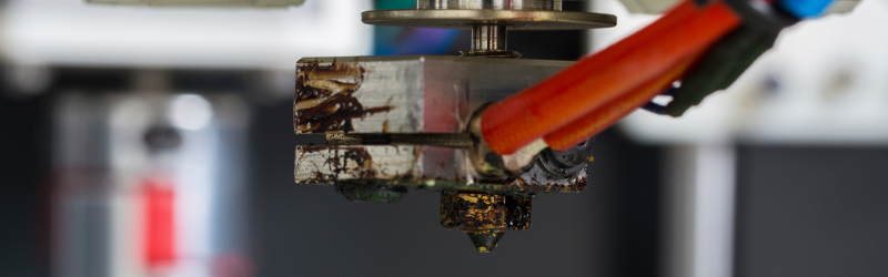
Manufacturers of 3D printers have a lot to do before they catch up with makers of the cheapest 2D, paper-based printers. If you’ve ever taken an inkjet apart, you’ll most likely find some sort of closed-loop control on at least one of the axes. The 2D printer will tell you when you’re out of ink, when a 3D printer will go merrily along, printing in air without filament. File formats? Everything is Gcode on a 3D printer, and there are dozens, if not hundreds of page description languages for 2D printers.
The solution to some of these problems are drivers – software for a 3D printer that slowly consumes the slicing of an object, printer settings, and placing an object on the bed. It’s coming, and the people who are responsible for making your 2D printer work with your computer are busy at work messing up the toolchain for your 3D printer.
The latest version of CUPS (C Unix Printing System) adds support for 3D printers. This addition is based on meetings, white papers, and discussions in the Printer Working Group (PWG). There has already been a lot of talk about what is wrong with the current state of 3D printer toolchains, what can be improved, and what should be completely ignored. Let’s take a look at what all of this has accomplished.
What CUPS Offers
![gcode to draw a circle [Image source]](https://hackaday.com/wp-content/uploads/2015/08/gcode-example.png)
Anyone who has ever dealt with a failed print will tell you this is not the case. Printers fail, sometimes spectacularly. From a white paper penned by [Michael Sweet] (PDF), lead developer of CUPS, driver support will include printer failures, a standard build platform, cameras, lasers, a replacement for the .STL file format, and the color of an object. It’s all there, an entire 3D printer toolchain, wrapped up in a single software package.
It’s somewhat remarkable when you consider what a user must do to print an object downloaded from the Internet. In the current 3D printer ecosystem, a user would download a model, set the temperture, of the hot ends and build platforms, slice the model, put it on a build plate, and finally send the G Code over to the printer. While this can be greatly simplified with fantastic host software such as Cura, a driver-like solution reduces all these processes down to a single, automatic step. Companies are interested, too: Ultimaker is already talking to PWG, and hopes in the PWG are high to get other printer manufacturers on board.
CUPS isn’t the only game in town, and in this case it’s a little behind the ball. In 2013, Microsoft released their 3D printing driver with spooling and queuing support, and an API for submitting jobs to manufacturers.
The Software is Ahead of the Hardware
While it may not seem like a necessity now, the problems being taken on by the CUPS devs and PWG are very interesting. A filament sensor before the extruder would solve a lot of problems found in 3D printers. When these sensors start appearing on printers, the software to make use of them will already be there. When UV resin printers make it big, CUPS will have support for it.
A 3D printer isn’t just G Code, and some layers of abstraction can make things much, much easier. With the features suggested for CUPS, we may soon have 3D printers usable by even the most technically inept among us. As long as we avoid the horror show of cheap inkjets and proprietary software stacks, this will be what takes 3D printing to every office in the world.


I’m not sure that the fact that GCode serves as a single unified printer control language for 3d printers is a “problem” per se.
It isn’t, and it solves a whole many problems that would crop up if you tried to do it any other way.
It’s important that the extruder path is pre-computed all the way through before printing, because if the path optimizer hits a snag or encounters some impossible point like trying to print over nothing, the software can warn you before sending the data over to the printer.
So, because you have to simulate the print on the computer in advance in any case, you already have a tool path description that matches your particular printer, in a format similiar to G-code, so why not just use G-code in the first place?
I agree with your sentiment, and with the article, to an extent. In my opinion, GCode is fine for driving printers as a standard output, and any driver that didn’t support it would be a joke. However, standardizing not only the instructions, but the delivery method, allows for the various projects that develop for 3D printers to work in ways that help each other by sharing improvements rather than try and steal business.
GCode is a good standard, but the problem is that it is an output format, which has been generated for a particular device implementation.
OpenSCAD is probably the closest 3D analog of Postscript, and would be good high-level language for the public exchange of models. Like Postscript, the description is high-level, and independent of any particular printer implementation.
There needs to be standardization in the middle layer (slicing software) that converts these high-level descriptions into G-Code that matches the user’s 3D printer. The first step should be standardizing the description of the machine capabilities for the slicing software/driver. This would roughly correspond to a .ppd (Postscript Printer Definition) file.
There should also be model-based hints, likely implemented as specially formatted comments (a la Postscript) included in the model file, that describe suggested materials or other rendering guidelines.
I agree. There are, and I’m sure will be many more, printers with very different limitations. For instance, some printers need temporary structures built to span large gaps (or start in the middle of nowhere), where as others have different filament for this (water soluble) and others yet (such as most metal fusing ones) have no problem printing over “nothing” as the dust powder underneath acts as a support until the print is “lifted” out of the print box.
It would be nice to have a file format that could be used on all types of printers and take the different feature and limitations of those printers into account. For instance
– metal-fusing printers have no problem printing on top of empty space due to the extra meta particles
– all fusing printers work best if “drain holes” can be added, but these are unnecessary for most extruder printers
– some printers use different materials for filler and supports
– one day we may have printers that can mix colors (die cartridges anyone?) on demand, I don’t think g-code can handle that yet
– there may eventually be printers that can remove temporary structures on their own, either through liquid submersion or automated mechanical/laser cutting
Yeah, but OpenSCAD describes the geometry, while Gcode describes the tool path. In other words, to describe the sphere, OpenSCAD uses just a single ‘sphere’ expression, while the printer needs a set of sliced circular paths for the object surface, plus fill paths for the interior—that’s why there’s the slicer software that calculates the tool path required to print your geometry. Technically, OpenSCAD geometry primitives could be used for both of those, but it would really be pushing a square peg in a round hole.
Using gcode as the lingua franca to talk to a printer is certainly a hack – the printer should accept a format that describes the object in some easy to understand fashion, and figure out a toolpath itself, rather like current printers handle postscript. Having it accept a format that literally describes the movements the print head should take is rather odd.
Three issues I see with that. First, you would have to ensure your printer has sufficient processing power to slice the object in a reasonable time. Two, you would need some standardization of slicing options to be able to communicate those to the printer. Third, if you do that you would limit yourself to just printers. GCode is understood by so many devices that it would make sense to leave it at that. Printers, cutters, routers, saws, all manner of CNC equipment that either currently only runs as a serial bus device with custom software, or uses its own custom hardware and driver setups.
You can’t take GCode generated for a 3D printer and feed it to a CNC machine and expect sensible results, so I’m not sure what the compatibility you’re worried about breaking actually is.
Actually you can (excluding delta style printers). Gcode is just cartesian coordinate system.
I think you’re missing my point. I said “and expect sensible results”, and unless your CNC machine has an extruder head with the exact same parameters attached as the original device, you’re certainly not going to get sensible results. The GCode generated is tied directly to the tool used, and to a degree, to the hardware it was used with.
All the delta printers I’ve seen take standard Cartesian gcode and do the transform to delta kinematics in firmware… A file that prints on a Cartesian printer should print on a delta, given that the extrusion settings agree (temperature, filament diameter) and the object fits within both build volumes.
No, it’s not “just cartesian coordinate system”.
Is your machine a delta printer, a cartesian 3-axis 3D printer, a cartesian 2-axis laser cutter, a cartesian 3-axis milling machine, or a cartesian 4-axis milling machine?
Even assuming it is a cartesian machine, how many axes does the machine have, how are those axes arranged, and what do those axes do? How are the home sensors and endstops arranged? What are the physical allowable dimensions of the machine?
What kind of “tool” is present, such as a milling tool, a laser, or a plastic extruder, and what kind of control G-codes are being sent to control those functions, such as extrusion of plastic, temperature control, speed control and direction of a milling tool, the size and width of different cutters and tools, laser power control, etc? All this stuff is separate from the basic control of cartesian movement.
You need to know a lot about the tool you’re using in order to generate G-code.
You can’t generate G-code and expect it to be portable to any kind of other cartesian tool.
You can’t even slice a 3D model to suit one printer and expect the resulting file to be portable to good prints on all other printers, because it incorporates that sort of hardware-specific information to tweak the extrusion and layer height and speed and temperatures etc just right.
Files like STL models, or DXF files for two-dimensional jobs, are the portable files – these can actually be given to different people with different machines with the expectation that you’ll get a similar product back.
It is much better to be able to tell the machine *what* you want and have internal processing power in the machine that determines *how* to do it in a way that is specific to that hardware.
It’s amazing that there are so many RepRap-style machines out there with 8-bit microcontrollers.
How many cheap commodity inkjet printers on the market have the same level of internal hardware, with an 8-bit AVR? We do need to move away from that.
I suspect eventually we will move away from the traditional familiar routines of slicing or toolpath processing on a PC, and we will send a 2D file such as a DXF, or a 3D file such as an STL, directly to the machine and the embedded processing power in the machine will take care of how that file has to be processed to suit that machine.
You also can’t necessarily take an Arduino sketch written in C or C++ and compile it as a program on a Windows machine and expect it to do anything… but the language is the same which makes developing for different platforms easier than having to learn a completely new language. Not to mention it makes things a little easier to port from one platform to another. I don’t believe Kratz was speaking of compatibility but rather ease of development.
A G-code file made for a 3D printer won’t work directly on a CNC machine only because the setup commands are different. The path description will be understood by both without any modification. All you have to do is translate the machine-specific initialization routines and it should work.
The difficulties only come if the CNC machine isn’t precise enough to follow the path, and if the extruder used on the machine is different.
But that’s hardly the point, because we aren’t trying to re-use G-code files from one machine on another. We’re generating the code each time for that specific machine’s parameters. The point is that the software doesn’t need to output ten million different formats for ten million different printers, or that we should need a driver in between to translate, becuse all the 3D printers and CNC machines speak G-code.
> But that’s hardly the point, because we aren’t trying to re-use G-code files from one machine on another. We’re generating the code each time for that specific machine’s parameters.
And that, in a nutshell, is why GCode bears no resemblance to postscript, as far as formats go.
> The point is that the software doesn’t need to output ten million different formats for ten million different printers, or that we should need a driver in between to translate, becuse all the 3D printers and CNC machines speak G-code.
Except that as you just pointed out, the GCode for one device is not going to work on another device. So you do need something to translate from an abstract description of the object to a series of manufacturing steps.
Also, stereolithography printers don’t take GCode, and I wouldn’t be surprised to find laser sintering ones don’t either.
“So you do need something to translate from an abstract description of the object to a series of manufacturing steps.”
The abstract description of the object is the 3D model before you slice it. What you’re asking for is some sort of standard format between the model file and the control code that is being sent to the machine, but such a format cannot exist because it would need to take into account the properties and quirks of each different machine.
And if it could exist, what problem would such an intermediate format solve?
Dax you just said “What you’re asking for is some sort of standard format between the model file and the control code that is being sent to the machine, but such a format cannot exist because it would need to take into account the properties and quirks of each different machine.”
They exist it exists, it’s a thing, it’s LITERALLY what a printer driver is.
Any program that wants to print talks to the computer’s printer service the printer service looks up the properties of the printer in the driver, renders the document, rasterizes the document and sends the data to the printer.
As I understand if you want to print a cube you have to model the cube, save your work, save as a non-native document compatible with the slicer, open the slicer, load the model, save the slices, take those over to your gcode generator, save your gcode, and send that to the printer.
At the VERY least a unified 3D printer system means being able to print from a native file format and not having to worry if you’ve got the updated version of the slicer compatible file.
“They exist it exists, it’s a thing, it’s LITERALLY what a printer driver is.”
A driver is not a file format.
My point, I suppose, is the type of abstraction used, and the level its used at. This is my explaination of what I feel would make the best system for this sort of thing.
1. From the low level device side, any CNC style machine would fall under a certain hardware class that would support GCode style commands and responses (could be much more integrated than just text over serial, but basically the same commands and data being represented).
2. From the OS side there could be several interfaces that take standardized data structures representing 3D models (3D printers), vector graphics (pen plotters, knife/laser cutters), or tool path data (routers), and anything else(chop saws, etc.)?
3. A device specific driver would sit in between, which would cover the translation from job data to GCode, utilizing options specific to the machine being utilized, as well as providing job monitoring and control interfaces. The driver would determine what types of data it can accept. However, since the underlying interface should be a standard, you could always implement a generic ‘pass-through’ driver to work with the machine directly from client software..
The above is very similar to how printing works in Windows. The obvious downfall being that you are dependent on vendor drivers to get the most out of the machine (potentially using generic drivers to work around this).
Also, one more point about why GCode would be the most acceptable standard interface to the hardware itself. Of the few large CNC machines I’ve seen, they all pretty much had an integrated desktop computer console on the machine itself acting as the contoller. (From Windows 95 to XP Embedded). The typical process was that jobs were ran upstairs by the engineers to generate all the GCode (or other design files, based on the machine), and these were placed on file shares that the machine operators picked up an ran. So the idea of thinking of a CNC machine or 3D printer like a plug and play USB accessory is slightly flawed when looking at larger scale machines, as most are workstations in and of themselves. (I’m not sure they way I wrote that it will make sense, but it made sense in my head).
It’s no different than paper printing machines. Many large commercial printing devices contain a DFE or RIP on a separate computer controlled. In what way is that relevant?
You seem to be forgetting that a 3d printer is just a light weight CNC machine. It’s on a completely different level compared to a 2 axis printer that only has to print a line of dots. G-code is industry standard when using CNC machines. Remember what CNC stands for? Computer Numerical Control. Even the million dollar, 9 axis multi-task machining centers accepts and uses gcode. To make a statement that gcode is an odd way of programing a cnc is rather ill-informed.
That’s about as useful as arguing that a printer is basically just a different sort of pen plotter. What the hardware resembles is more or less irrelevant, and my point wasn’t even about GCode specifically: it’s that sending instructions at the level of motion control to a 3d printer is way lower level than it needs to be, and in fact makes portability between printers more difficult.
“printer is basically just a different sort of pen plotter” Umm it is?
And a kiln and a home oven are basically the same device – but that doesn’t mean that insights about the user interface of one have any usefulness when applied to the other.
An inkjet printer isn’t a pen plotter. A pen plotter is more similiar to a 3D printer than a laser/inkjet printer is.
The printer driver is mainly concerned with how to stream a bitmap over a cable into the printer’s memory and that’s it. Each printer has its own data and command format, which makes this task difficult, and which is why common languages like PostScript were developed.
The “PostScript” of 3D printers and CNC machines, is G-code. It’s that simple.
> The “PostScript” of 3D printers and CNC machines, is G-code. It’s that simple.
That’s plainly not the case. Postscript describes how a printed page should look. GCode describes a specific series of operations that a specific type of printer can execute to create something. GCode resembles the bitmap formats of some printers far more closely than it does postscript.
@Dax
But is G-Code, as it stands, as transportable as PostScript?
The G-Code I generate for my mill appears dependent upon my machine (I wouldn’t dare use it on someone else’s machine unless they were identically setup) as the G-Code contains artefacts of my device configuration such as feed-rates, cut depths, spindle-speeds, etc.
Now, I suppose if someone was to define a “generic device” in G-Code, such that all programs that output the code, output it for this (theoretical) device, then at least every driver knew how they could translate it into the (equivalent) G-Code that the specific machine requires.
But at that point, why go down to G-Code? Is there a more easily translatable level? (DXF?)
“But is G-Code, as it stands, as transportable as PostScript?”
Does it need to be?
Why would you ever try to use a G-code file generated for one printer on another printer?
When the G-code for a print is generated, you have to mind the nozzle size and other machine specific parameters when figuring out the path, so you have to slice the model and generate the file again anyways. The question here is, why invent another new language for the output format when we already have G-code and every machine speaks G-code?
“all programs that output the code, output it for this (theoretical) device”
There can’t be such a generic device, because the extruder path depends on the filament/nozzle size. You can’t actually pre-slice and tool-path a 3D model in a way that it would be printable by all machines even if you did have some different code.
“it’s that sending instructions at the level of motion control to a 3d printer is way lower level than it needs to be”
G-code isn’t motion control. It’s path description, much like vector graphics, and the machine itself decides how it will traverse that path.
The path description is important for things like infills, because if you just send the image of the slice over the wire, the printer then has to optimize the path on its own and if the algorithm does something silly – too bad – the object is already half the way printed. Whereas if you send G-code you can pre-compute the optimized path through the slices and the printer doesn’t need to. Your pathfinding software can leverage the greater processing power of the computer and it can show you if there’s any problematic spots before you start printing it.
If you have a photolitographic printer, sending G-code over isn’t a problem because it just renders the information into a bitmap in its own memory and flashes that onto the build plate. It’s trivial to translate from G-code to bitmap, but hard to go the other way.
I think the argument really boils down to where abstraction and code generation occurs.
In current printer models it goes something like this:
*.docx > printer driver/*.ppd file > printer > motion/color/etc. generation > printed page
Having G-Code as the common code output by the driver would go something like this:
object file (dxf/vector/bitmap/etc.) > printer driver > motion/color/etc. generation > printer > printed object
This means that the printer is only responsible for handling the motion file and its output. The driver handles everything and the printer only handles execution.
What everyone who is apposed to this is arguing for is a similar process to traditional printers where it would look like this:
object file (dxf/vector/bitmap/etc.) > printer driver > printer > motion/color/etc. generation > printed object
Using G-Code as the standard output means that 3D printers will be stuck where they are computationally and development on that front will be largely ignored. It means that more complex tasks must be handled by the host computer rather than by the printer. This might not look like a problem until someone wants to make a printer that can do its own QA/QCs. In the former order (yours) the printer that can only take G-Code doesn’t know what the object must look like and therefore must ask the host if the checks have passed. This means more time and wasted money (because time=money). I could go on about the problems with moving processing intensive work to a host computer, but I’ll let it be…
It’s not an odd way of talking to the 3D printer at all it’s the large varied and inconsistent chain of applications between the print button in Blender (or whatever) and the gcode output that needs streamlining and the way or complete lack there of that the printer talks back to the computer.
In printer terms imagine if you had to save anything you wanted as an .eps load up a rasterizer, enter the characteristics of your printer by hand, rasterize the .eps, manually load the paper, manually zero the print head, open the ink cartridge and manually check the ink level, make sure the printer software is ready to receive, then send the raster file to the printer.
That is so much worse than opening a text document and hitting print and letting that be taken care of for you but for some reason some people like an equivalent state in 3D printing.
And you get to change layer height, infill, support just like dpi resolution, color intensity and margin!
Your analogy falls short of reflecting the reality of printing FDM. I’ll expound;
“Imagine you had to save anything as an .eps” – 2d prints are easy to describe in a variety of formats and deciphering txt, pdf, rtf, postscript, jpg, png, etc. is easy enough to encapsulate into a subroutine when your target output is, basically, three or four hex values in a matrix on a known geometry, predefined by an industry that’s existed for hundreds of years. You’re literally throwing a spreadsheet at a flat surface.
In 3d printing we get, basically, 3 formats (EMF, STEP, STL) that slicers can recognize and decipher, with some holding more information than others. STL, for example… doesn’t actually contain a scale. We just assume mm but it’s not strictly defined, and there’s no color info per-object. Some of them have the ability to store arcs as part of their geometry. Some are strictly polygon. Not all slicers or printer firmwares are capable of interpreting ARC commands. We’ve had a lot of freedom developing these systems, and it’s still a wild west. If you tame that wild west, you WILL stifle innovation. I would hate to see projects like klipper/mainsail/marlin narrowing their focus to try to constrain i/o to a standard defined by any one manufacturer.
“load up a rasterizer, enter the characteristics of your printer by hand, rasterize the .eps”
If you’re trying to parallel the experience of slicing a model – For the most part, we don’t need to enter the characteristics of our printer every time. We DO have to make changes to the profile if we’re using exotic filaments or whatnot, but the same is true when you use exotic mediums in 2D printers.
You don’t use the same settings for photo paper or transparencies as you do for regular paper, for example.
The “rasterize the .eps” function is the only part that happens automatically in your 2D print driver and it’s where all the nuance is necessary and usually requires hands-on user attention in 3D printing.
Even still, I have profiles that I’ve set up and tuned for PETG, PCTG, PLA, HTPLA, etc. that are just drop-downs in my slicer… The same as selecting, for example, “labels” as a paper type in my 2D print driver…
“manually load the paper” The build plate? I don’t know what you mean here. Does your 2D printer automatically refill it’s own paper cassette?
“manually zero the print head” I don’t know many people who still need to do this, and I rarely had to do this even before ABL systems existed. Certainly not with every print. I have an inkjet, though, that makes me print three fkn alignment sheets every time I replace it’s ink…
“open the ink cartridge and manually check the ink level” There’s no fair equivalent here. The 2D printer just has “ink” in a container of some sort and lies about how much is in there. 3D has literally hundreds of different mediums. Almost all printers have runout detection so this isn’t even technically necessary for most.
For the 2D print experience, you’d need a printer with a proprietary slicer inside an encrypted mainboard, four colors of one specific type of filament that you couldn’t change, and no ability to print if one of those colors (drm protected) was low enough that the printer decided that spool was “empty”. For the full HP experience, your printer would have five colors, three of which would be in one cassette that you’d have to replace if any of the colors was low. The other two would be slightly different black colors and would not allow you to print if the color cassette was missing or from a brand it didn’t like, or even their own brand if you accepted their latest firmware that said you’d only use their subscription cartridges.
For SoMe ReAsoN some people like an equivalent state in 2D printing.
That’s the job of the PC software. Because we have these supercomputers sitting round on our desks, while the printer is only running an 8-bit microcontroller. Makes sense.
We could add brains to the printer to do all that. But why not just use the PC? Indeed that’s the way 2D printers went. From emulating Epson to Postscript and whatever else, to being directly driven over the parallel / USB port. Taking brains out of hardware is the cheap way of doing it. Just consider the PC part of the system, it’s really good at it!
What might be good is some sort of intermediate standard. Like the OSI model that’s let networking grow like it has. Then again, why not just exchange the models themselves? Like happens now. There’s already open formats for that. Things are fine. Some standardisation of the software might be useful, again in an OSI-like layer model. But leaving the calculation to the enormously-powerful calculator that is a PC is sensible, and economic. It’s also easier to update software on a PC, no hell of incompatible or outdated drivers for the printer, because it’s bare-bones minimum.
Ironically most printers don’t accept Postscript. The PC boils it all down to simple commands for the printer’s cheap little controller. It knocked a lot of money off the price of printers, particularly a few years ago, before powerful cheap systems-on-chip were available. Remember how much laser printers used to cost?
Why?
Proprietary intermediary processing can only serve to make the machine less adaptable and less, ultimately, approachable.
This seems like an argument for convenience that sacrifices basically everything else. Just run a slicer and make good decisions.
Dont hold your breath waiting for response. Youre posting to a decade old discussion.
>this will be what takes 3D printing to every office in the world.
Why? It’s not something meant for every office in the world. It’s a rapid prototyping device and people using it want control!
What would a normal user 3d print anyway? A coffee cup?
+1
the toolchain of 3D printers is the same as for nearly all cnc manufacturing machines. In my opinion there is no need of pressing the toolchain of normal printers on a 3d Printer, as long as they are not as necessary as lets say a normal printer or a microwave.
Paper printers closed a need of producing an infinite amount of sheets with an limited amount of physical parameters while 3D Printer close the need of producing an limited amount of objects with an infinite amount of parameters.
a good solution for “offices” would be a standalone machine that gets fed with the 3D data and does everything else by it self with the capability of using the existing toolchain for more control of the process.
And like RandyKC said: a closed loop control as a standard is the next big step to make!
Pretty much this.
My favorite analogy: you don’t see people printing out ebooks onto paper, but paperbacks still sell well. Yet most every home has some sort of printer.
I’m going against the geek hivemind, but The Diamond Age is still very far away.
That’s because there’s a crucial features missing. Ordinary printers waste a ton of paper to print an e-book because they don’t do double side, and you end up with an awkward letter-size stack of paper that is difficult to use. It would take too much effort to split the book into folds, print them on both sides of the paper manually, and then fold and glue them into a proper book.
The paper and toner also ends up costing 4-5 cents a page, so printing a 400 page book two pages per sheet would actuallly cost you about $10 which is what it costs to buy the paperback.
I’m assuming that a ream of 500 sheets of decent paper costs $5 and a toner cartridge that prints 2000 pages costs $80. That makes exactly 5 cents a page.
Incidentally, I have made a custom book on an ordinary desktop printer. If you do double side and fold, you can fit four pages per sheet, but the toner is still the most expensive part so it isn’t that much cheaper.
The concept is simple: you print, fold, stack and dip the spine of the book in epoxy glue, then press it onto a cardboard sheet which folds into the covers. In practice it’s tedious to print pages in jump-step order: 4-1 flip 2-3, 8-5 flip 6-7… because ordinary office software doesn’t support printing the whole book in one go for folding. The other problem was that the printer didn’t center the two sides properly, so I actually had to find the offsets where a cross printed on the “center” of the sheet would overlap at the other side, and then center the pages to that offset so that the sides could be folded together. The offset put the fold off-center on the actual sheet, so the edges of the sheets didn’t meet when folded and I had to trim each fold.
It was plainly obvious that the printer wasn’t designed for printing a book. Needless to say, my book wasn’t very long.
Way back before I got a Handspring Visor Platinum, I printed out two ebooks so I could read them without having to sit at my desktop computer.
I found an addon for MS Word that printed 4 pages to each side of a sheet of paper and it could be set to print half the pages, then flip and feed the stack back through to do the other sides, fingers crossed it didn’t grab two or more sheets and screw it all up. Didn’t have a laser printer with duplexing, it was an old Qume CrystalPrint which used a halogen tube and an LCD shutter bar, made back when there were still active patents on the process of using a laser to shine on the photosensitive drum.
Then I cut the pages a few at a time and used some flexible glue to bind them. After all that I was ready to read.
It really was way too much work. I went back to sitting at the computer to read until I got the Visor, followed by a Tungsten E2, LifeDrive, Epic 4G, Photon Q and now a Galaxy S4.
“What would a normal user 3d print anyway? ”
Replacement parts for anything that breaks?
Once you already have a 3D printer that prints as easily as a 2d one, the use-cases for it go up quite hugely.
At the moment, the inconvenience of them outweighs a lot of uses where there is other options.
Even the coffee cup example – at the moment its stupid to do so as the cost/effort is just too much.
But if effort was zero, a 3d printer becomes a bit like fast food – you use it when you cant be bothered to go to a shop to get a (anything plastic you need). Dont underestimate the pull of convenience over quality or cost.
(ok, a coffee cup has health issues here, so not really workable – lets say paperclips, wire tidys, pen holders, whatever….lots of things we use are really just shaped plastic)
I have use-cases pop into my head regularly. One of which is a set of clips that would secure a smaller box fan into an open window. There isn’t much design work to be done, and finding something like that on the open market (for such a specific purpose: my box fan, my window) is nearly impossible.
The trouble is that the replacement parts will probably need to have certain physical properties, which means that you need to think about how to position and slice it to achieve those properties, which means it’s never going to be click-and-print across all printers.
Plastic replacement parts. Most of plastic parts in consumer use are so thin they break easily, even tough the material has better qualities. A wider PLA part is a solid upgrade most if the time.
Closing the loop by adding encoders need to be the next step in consumer DIY 3d printers. Developing software drivers won’t solve a hardware deficit.
Congratulations, you’re the ten-thousandth person to suggest that 3D printers need closed loop position control. You’re welcome to be the very first to prove that closed loop control improves cost and performance vs. using open loop steppers.
It does improve process reliability.
Its not just about the position control, you also need one for the filament to get reliable results.
idk why the only closed loop should be the heating of nozzle and bed.
I have a few ideas but it takes time to realize them and until then i have to live with monitoring the print in person…
I agree with you there. Calibrating the filament feed rate is a pain given that there can be variability in hobbed bolts. A separate wheel measuring the filament feed distance would be a welcome improvement over relying on e-steps.
I was making an assumption that most of the talk about adding encoders to 3D printers implies sticking an encoder wheel to the back of a cheap geared DC motor to replace the slightly pricey steppers. The fact is that steppers have their precision baked in at the factory, which is the unspoken cornerstone of hobbyist 3D printers. Breaking that reliance on this prefab part may be interesting within the scope of the RepRap project, but IMO isn’t worth the trouble given that there are more pressing problems to solve.
Now, figure out how to measure absolute volume of extruded plastic, including drool and missed steps, and you’ll be a community hero.
A DC motor would also allow cheap, semi-closed torque control loop (measure current), which should help with keeping constant pressure in the extruder and thus constant feedrate…
@AKA the A: That’s not closed loop enough, though. To literally close the loop you would need to track the motion of the filament. Without that the machine is blind and guessing as to what it is doing.
http://link.springer.com/chapter/10.1007%2F978-3-540-71439-2_6#page-1 This might be of use, the full text is available elsewhere free.
Position control as I mentioned in another comment, is a done and dusted topic for the most part in control theory.
No need to prove what the market already knows. I also don’t always go with the crowd, but 10000 people are most likely correct.
Continuing to build on a flawed foundation of open loop systems will never achieve the reliability of the 2d printer market.
Do you want to change the 3d printer world?
Develop or adapt cheap 2d printer motors/encoders for 3d printers.
Using a quadrature encoder for the filament is easy and improves reliability. Adding a sensor for the extrusion is harder. Both are needed for reliability.
Neither has anything to do with software drivers, because the closed loop control isn’t exposed outside of the device. The machine still eats G-code and produces discrete steps at the motors.
Why not use a laser mouse sensor?
…
I think I’ve found my next project.
https://hackaday.com/2015/01/20/closed-loop-control-for-3d-printers/
You are ramming against an open door:-)
Most of the problems I have with 3d printers don’t have anything to do with just software. My biggest issue is that there is no feedback on knowing if the print is proper. I don’t mean checking for filament, that would be terribly easy. But check that the part stuck well to the bed, check that there are no layers detaching, check there is no mess created etc.
I don’t know what is all the fuss about feedback on the motors. Run them withing their capacity and they will not do wrong. However i have seen plenty of people that have no idea how to adjust the current in their driver and wonder why it misses steps when their 3A/phase motor gets 0.3A. Even the store i got my kit for said they don’t bother adjusting the current. And guess what: not all drivers are adjusted the same from start.
The fact is that a 2d printer is so much simpler to control closed loop, and even if the problems are solved and I can replace the $10 stepper and $2 driver with a $2 motor $2 driver and $2 controller, i will not save much money. The whole concept of the way a 3d printer works, depositing layer by layer is slow and deflective by nature.
I’m working on trying to solve that right now.
You shouldn’t need any more than a webcam. ?!
With a calibrated camera (checkerboard), you can tell what position your camera is in. Once you do that, you can then load software that takes the state of the print and then overlays it over what the camera is recording. If the print is “out of whack”, the camera software can halt the job and send you a message.
Mills have something very similar, with a auto-visual inspection tool.
Thing is, that a big CNC mill will do damage going into hundreds to thousands of $$$ (possibly even more) if there is a fuck up, so it’s literally worth it to buy such a system (pays for the pricy SW development), a crappy 3D printer that can’t even damage itself…not that much potential to cause expensive damage, so somebody would have to do it for free…
I don’t think it is possible for the printer to damage itself unless there is some sort of sw problem with the controller. The only things i can think of is overheat or move the motors past their allowed position.
That is a great idea, @jwcrawley!
I am using OctoPi as a server for the printer and it already has a camera in place, so I think that might make it easy.
I am just wondering now if there is another way to detect errors….
You could have it home in on endstops (if physically possible due to printed part) periodically, and count the steps it took vs the steps it should have taken, if the two are different, something went wrong…
Homing on layer change was an option back in 2010…IIRC. It was abandoned because it wasted too much time and there were many other things causing bigger issues.
Personally, I just set the current of the drivers and don’t run the machine too fast (most of my machines can safely run about 2x the speed that I actually print at).
I thought the implementation of at the very least PID control to the actions of 3D printers. Rather than depending on open loop control systems, and stepper motors. Especially since a great deal of control theory already addressed movements in cartesian space.
I’m neutral on PID control loops.
They can potentially make everything more difficult, yet can also eliminate error in the system.
I’m wondering if a high DPI chip from an optical mouse would be sufficient enough to be put against the belts to watch for motion. Those devices certainly give direction, and are of good quality. And they’re cheap.
The next question is: How do we hook up 2 of those to the RAMPS for PID? And also, what is the CPU/RAM cost on the Arduino Mega?
C Unix Printing System? I thought it was common?
“The “PostScript” of 3D printers and CNC machines, is G-code. It’s that simple.”
Absolutely wrong !!!
Postscript is still very much abstract from the printer mechanics.
For example, sending a postscript command set to print a line 2mm thick from [100, 100] to [300, 400] will give the same result regardless of if the printer is laser, ink jet, or any other mechanism for getting the image on the paper.
GCode is a direct mechanical control language.
With Postscript the printer is still responsible for taking the commands and converting them into sets of motion of a laser, print head or whatever in order to get the correct result.
GCode is a direct control over the end mechanism.
In theory a Postscript interpreter could generate GCode for your 3D printer, but only if it knew very detailed information about your 3D printer, and GCode generated for your printer would give the wrong results on my printer.
Postscript on the other hand would look the same on both because the final step of converting to actual business end control is very much device specific.
but isn’t that what a 3d file is for?
Actually I believe PostScript can. PS is fully Turing complete stack based programming language. If the PS driver is informed how to translate page to G code and every page would be one layer. And layers could be just key layers.
To print a pyramid, draw square in page one, dot in same place on page two and tell the difference in height of the pages. Maybe twenty lines of PostScript.
Then let me rephrase: stl is postscript for 3D printers. Objects are created in cad and transferred into the universal stl that every printer software takes. Problem solved.
If 3D printers had the built in capability to do their own slicing etc and could take STL directly, that would be very nice. The printer would also need some scaling settings due to some 3D modeling software not correctly tagging the STL output with the proper scale information.
Hi! Just spent a lot of time with regular 2d printers and their software. Postscript is not used a lot any more. Pcl is language used in most printers. Postscript is available only on very expensive printers as the printer is usually responsible for rendering and this requires a lot of processing power on the printer. In pcl stuff is rendered before it is sent to the printer.
But a language that can describe objects being sent, combined with the gcode and some status feedback would be a nice 3d analogy of what pcl does….
Sending an stl file over to the printer would be a nice analogy for postscript…
Just my 2 cents…
PS is scaled independent, the printer is responsible for rendering in its native resolution. Everything is scalable in PS so easy to resize for any output device that can render it, be it a printer or a LCD
@Steve : Agreed :) STL is target agnostic and describes the problem to be solved, not how to solve it. GCode is just too low level.
@Fireclocker : But it wouldn’t be the same on every printer. If one printer had a finer laser (say 600 dpi) than another (say 100 dpi) then the pyramids would be slightly different. If the pyramid was made up of solid layers then on one printer it might have gaps and on another have too much overlap. Nobody is saying you can’t convert PS to GCode, but to do it the PS interpreter must be given knowledge of the target so that the GCode can be crafted for that very specific output mechanism. This means the GCode needs to be different, hence cannot be used as the target agnostic data.It doesn’t describe the problem (i.e. a pyramid) it describes how one specific engine needs to behave to get the desired end result. It would certainly be possible for a 3D printer to take postscript though (height calculations would need some thought) but for a single slice it would work since PS describes the desired result and the printer receiving the PS would know its own characteristics (nozzle size etc…) hence could workout how to get from PS to head movements in order to ‘do it right’
I think Postscript Printer Description format covers some of that.
If you ever took a look at the thing the computer sends to the driver, it’s even more low-level than g-code. I’ve worked with epson 2d printers and it’s full of: move to 100, 100; print_dots 000111001101011100111; move to… and so on.
In a 2D printer the driver takes a postscript file, transforms it to a hardware control language (ESC/P) and sends it to the printer.
In a 3d printer the slicer takes an STL file, transforms it to gcode and sends it to the printer. So STL = postscript, slicer = driver, gcode=esc/p. No need to change anything, it’s as it should be.
This is more or less what I was going to say.
That said, STL sucks and a better file format would be much appreciated. (attributes like color, material, maybe tolerances, etc)
What absolute bollocks. The only computers that need drivers are windows based pieces of crap that have trouble communicating and this is mostly as micro$oft refuses to adhere to standards and has to proprietize everything making it unreliable and (ironically) incompatible.
3D printers already have a standard language and protocol, there is no need to change it.
Er, no. Drivers are a basic part of OS design. Here’s the Linux kernel’s (massive) drivers subtree, for instance: https://github.com/torvalds/linux/tree/master/drivers
A fine idea. But let’s not forget about the 2D realm. This same sort of interoparability needs to be brought to the realm of 2D laser cutters. Laser cutters are the absolute god damned workhorse of any makerspace, and any architecture lab these days.
And dealing with them can be HORRIBLE. Dealing with PS, PDF, DXF, and then the applications like AutoCAD or Illustrator to try and get some sense of a physical layout properly submitted to the laser is a freaking nightmare right now.
I’m not saying Universal Laser is a bad company, they have been helpful, but their software just falls short. There needs to be a closer bridge between AutoCAD and their laser management interface. And, really, if there was a laser-cutting equivalent of Acrobat Reader, that could really change the landscape. Something free, something that is purpose built for lasers, and that cutter mfg’s can build inter-operation with. Batching, queuing, layout, import, fixing, python hooks for automation, etc.
Dear Brian,
“Anyone who has ever dealt with a failed print will tell you this is not the case” – Bollocks, mate.
You should stop talking about 3d printers; you clearly have no experience.
Last month they were too expensive for you (at less than £300!), now they’re too hard for you to use because you can’t just press “print” and have the perfect model come out on a silver platter.
They need the experienced user to be able to set higns like hot end temperature and speed, because you need to change that stuff. And you need to know that you need to change that stuff.
Makerbot and Stratasys have tried to take the user out of the loop, and the result is expensive and inflexible.
Printer drivers are what’s responsible for demanding a new cartridge after x pages, or randomly deciding it’s time to print 1 line of garbage across the top of every page in the paper tray. We don’t need that. Shut up Brian.
Since it hasn’t been mentioned. Check out Micro3D. It simplifies the print process. The software makes it really easy to print. Even un/loading filament is easy. This printer I have no issues starting a print and walking away.
Dear Brian,
That’s what a slicer is, it is the driver. On the other hand, If you want a painless, brainless box, that spits out drag and drop that’s another matter entirely. Buy a big name commercial machine you will get good prints and an AutoCad or Solidworks plugin that does what you are asking.
The problem with hobby 3D printing is simply that hobby machines are made as cheaply as possible. Cheap bearings, flimsy designs, shoddy filament and diy software. A magic driver is not the solution to that, time is. Steady improvement is happening and it really is amazing how much progress has been made in a short time.
CAD/CAM/CNC are mature, widely used and well understood by legions of professionals. Professionals who manufacture the cars you drive, the tools you use and the consumer products you are surrounded with.
What you are advocating for sounds a lot like the home embroidery market or craft cutting, before people got sick of canned designs and ridiculous vendors like Provo Craft who sued the makers of SureCutsALot software for violating their screw the consumer business model.
The problem with the folks saying “we need 3d Postscript” is that they have NO IDEA what happens when you send postscript to a printer.
if you send Raw Postscript to a printer, you are just as likely to get reams of garbage out of the printer as you will a readable page. – This isnt the part we’re missing.
we NEED the 3d printer equivalent of “PPD” files. the necessary parameters for “this specific printer”
a Postscript file without the proper PPD(postscript printer description) file, is exactly what we have with 3d printing today.
EVERY printer has different behaviors, different quirks, different options, even amongst identical makes of printer, and feeding Raw files gets unintended results because there is no software defining the performance of said printer.
the Slicer programs really are just an environment for perfecting YOUR Printers’ variables. (they’re a manual PPD generator for lack of better analogies)
Until 3d printers get 10x more reliable, and it isnt a checklist of “did it adhere, is the room warm enough, did that layer stick, is this filament thinner/thicker than the last round .. etc etc etc” – Its a matter of reproducibility and reliability, and 3d printing .. hasnt “gotten there” yet, there are way way too many variables for it to be anything but a Technically inclined persons project.
when the variables are all measurable, then we can look at software drivers, and printer description files and move to a more “postscript” like 3d printing environment, but for now, it absolutely isnt an issue that can be solved in software, its entirely a hardware variance issue.
What are computer drivers and why are they used.
http://www.dailymotion.com/video/x2fkpg
Working link
http://www.dailymotion.com/video/x2fkpgi
My impression is still that the 3d printer just works, and is easy to use. The paper printer is on a roll though, and there has been at least three prints without issues!
Maybe it will stay connected now that I’m not using windows any more..
Either way using a 3d printer is still easy, and getting good results is still difficult. Might be marginally simpler with bamboo but they seem to be shady like HP so a bad option either way.
The upside is that if you spend some time learning and having a good time and socialize about your idea you will most likely arrive at a pleasant result, pretty simply.
Be careful with adding 3DP support to CUPS!
If someone adds that to CUPS, it would become a mess of code spaghetti …