You probably know that to transfer the most energy between a source and a load their impedance needs to match. That’s why a ham radio transmitter needs a 50 ohm antenna (at least, usually). The transmitter is 50 ohms and you want a match. Some test equipment matches impedance, but for multimeters, oscilloscopes and a lot of other gear, the instrument just presents a very large impedance. As long as it is much larger than the measured circuit’s impedance, the effect will be small.
With today’s MOSFET instrumentation amplifiers, it isn’t uncommon to see very high input impedances. However, you sometimes run into something that has a low input Z and that can cause issues if you don’t account for them. On the other hand, where some people see issues, others see opportunities.
[Paul Allen’s] SigZig data logger is a good case in point. It has an input Z of about 330K ohms. Not as high as a modern scope or digital volt meter, but still fairly high compared to what you usually want to measure. The SigZig has a very low noise figure, so the guys at SigZig decided to see if they could exploit the 330K input Z to measure very small currents.
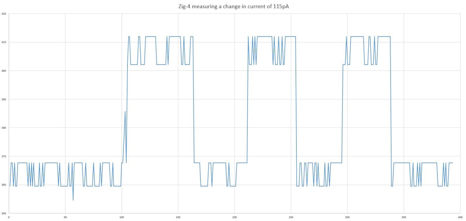 Using some basic math modelling they were able to dectect 115 picoamp changes. The plot on the right shows the difference between a 1 gigaohm resistor and a 1.1 gigaohm resistor loading a 1.25V source. You can see there is a little noise, but the signal is clearly discernible. Obviously, without the low noise floor, it would be difficult to pull the signal out of the noise at this low level. But as we’ve mentioned before, the SigZig is very quiet. If you need a brush up on impedance, we’ve got you covered there too.
via [Dangerous Prototypes]


This is an area of electronics I’m still fuzzy about.
If we’re dealing with gigaohm level of resistances, how do you calculate air, which is around 1.30~3.30×10^16/meter? For a short run, say 1 mm, you’re still dealing with 10^12 ohms. How do you model this?
I’m sorry this won’t answer your question, but I’d say the cheaty way is to avoid this from happening by having a large enough air gap. Air resistance depends on lots of stuff like humidity, pressure, temperature or composition (think somethink leaking chemicals nearby) so you’ll likely think for the worst possible case, space conductors a lot more than that, and stop thinking about it
Put it another way to answer your question, you need to make sure a lot of parameters are kept at bay before you can model it, which may work in controlled environments (oil insulated stuff like condensers, high voltage transformers…)
That makes a good deal of sense. Thank you.
It’s impedance, not resistance. The resistance of air is huge, but at AC, the impedance of air approaches that of free space, which is 377 ohms. Impedance comes from inductance and capacitance per unit length, and even though air can’t conduct electrons below dielectric breakdown, it can still store charge and magnetic fields.
Whoops, I think I misunderstood the original question. Thrown by the article (and the linked article) talking about impedance, whereas really they’re talking about resistance..
I’m far from an EE, but, I don’t think you do. Unless you work with HV it’s not really an issue (?). I think for the most part it’s just ignored since there are bigger effects at play (mainly EMI) until you get close to the breakdown voltage of air.
Unless your question was, how do we know the resistance of air. Which I would reply: empirical data. Some famous scientist sat in their lab all day making sparks, measuring voltage and current.
“You probably know that to transfer the most energy between a source and a load their impedance needs to match. That’s why a ham radio transmitter needs a 50 ohm antenna (at least, usually). The transmitter is 50 ohms and you want a match. ”
No. Both the transmitter and the antenna were designed to look like 50 ohms impedance toward the coaxial cable connecting them, because the cable impedance has been chosen to be 50 Ohms impedance back in 1930’s
http://www.belden.com/blog/broadcastav/50-Ohms-The-Forgotten-Impedance.cfm
http://www.microwaves101.com/encyclopedias/why-fifty-ohms
I’m not sure how this negates anything I said. I wasn’t talking about WHY everything was chosen to be 50 ohms. Just that the Z has to match and it is usually 50. Of course, back in the old days we used 300 ohm ladder line and some people still do with appropriate matching networks. CATV is usually 75 ohms. So yeah, there’s some historical reason everything in that area is 50, but that doesn’t negate the statement that you want a matching source and load for maximum power transfer and that most ham transmitters and antennas present a 50 ohm Z. And, of course, there are some antennas like the inverted vee that give you “close to” 50 (link an inverted vee) and you just live with the slight mismatch.
Interesting links though. Thanks!
Also, the matching impedance is required for maximum Power transfer, not Energy transfer. A bigger energy can be transferred without matching the impedances, just it will take a longer period of time compared to the situation where the impedances match.
Fair put.
Yes max power is transferred with matching resistance/impedance. Most people are surprised to find though that at max power, the power dissipated in the load is equal to the power dissipated in the source. In other words, power supplies and transmitters (and batteries) get hot for a reason.
A power supply is the last place where you want impedance matching.
A well-designed power supply operates far below the maximum power point, in a range where its output impedance approaches zero. That makes the voltage more or less immune to changes in the load, and ensures that almost all of the heat is generated by the load. That’s why you choose a 5v @ 1A power supply to run a circuit that wants 500mA. The 5v @ 1A spec for the supply doesn’t mark the supply’s maximum power point, it marks the point where the supply’s output impedance stops being acceptably close to zero.
Power supplies get hot because of non-ideal behavior that lowers the transfer efficiency, not because they’re tying to achieve maximum power transfer.
Maximum power transfer matters when you only have a finite amount of power in the system, can’t add more, and want to make what you have go as far as possible as fast as possible. If we apply that idea to a battery, the maximum power point is achieved by a load that does the most work while draining the battery in the shortest time.
You’re in good company for misunderstanding the maximum power transfer theorem though. Even Joule made the same mistake. It was Edison/Upton who showed that you want maximum transfer efficiency instead, and that you approach maximum efficency as the power dissipated by the supply approaches zero.
Sounds like a device begging for a Sigrok driver.
According to the open source application they released, the device identifies as serial adapter. It talks at 57600bps. Commands are a single character each and take one or two 1-digit parameters. Samples for all channels are reported on one line separated by commas.
The Zig-8, Zig-Pro and Zig-HS (200k samples per second) will/are native USB in order to take full advantage of their capabilities. A lot has changed since the CES video that they posted. However I personally was adamant that the Zig-4 be serial. The reasoning behind this is that I wanted it to be dead simple for anyone to interface with it, even if only with a terminal. I was also imagining things like simple Python scripts for the Raspberry Pi or similar. Also since the Zig-4 isn’t the fastest, serial wasn’t much of a limiting factor for speed.
I assume that graph x axis is in seconds? Thermal noise for those resistors is around 130 uV. How many bits are the converters? What kind of gain is used? Anyone care to add the shot noise for 115 pA and the bandwidth required (or integration time or minimum sample rate) for a reading valid to 95%?
The X axis is number of samples and it was running at about 3 samples a second. The converter is 18 bit. The gain was set to 8 but calibration hadn’t been done for that gain so the actual voltage values (in uV) on the left are somewhat invalid. The main point was just to show that it could detect the change (repeatedly) and not necessarily about absolute readings. As far as noise: http://hackaday.com/2015/01/25/when-adding-noise-helps/
Sorry to zombie post.
I just found this information and am interested, but it seems that this product is no longer available, or never made it to market.