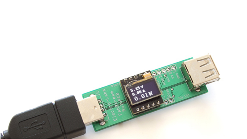
The USB interface is being increasingly used as a power supply and charging port for all kinds of devices, besides data transfer. A meter to measure the electrical parameters of devices connected to a USB socket or charger would be handy on any hacker workbench. The folks at [electro-labs] designed this simple USB power meter which does just that.
The device measures voltage and current and displays them, along with the calculated power, on the small 0.5″ OLED display. The circuit is built around an ATmega328. To keep the board size small, and reduce component count, the microcontroller is run off its internal 8MHz clock. A low-resistance shunt provides current sensing which is amplified by the LT6106 a high side current sense amplifier before being fed to the 10 bit analog port of the ATmega. A MCP1525 precision voltage reference provides 2.5V to the Analog reference pin of the microcontroller, resulting in a 2.44mV resolution. Voltage measurement is via a resistive divider that has a range of up to 6V. An Arduino sketch reads voltage and current data on the analog ports and displays measurements on the display. The measured data is averaged to filter out noise.
The OLED display has a SPI interface and requires the u8glib library. The project uses all SMD parts, but is fairly easy to assemble by hand and could be a nice starter project if you want to wet your feet on surface mount assembly techniques. It’s designed using SolaPCB EDA software, and the source files for schematic and board layout are available as a ZIP archive. Download the BoM and Arduino code and you have everything needed to build this nifty device.
Thanks to [Abdulgafur] for sending in this tip. And if you are looking for a more comprehensive solution, check the awesome Friedcircuits USB Tester which we reviewed earlier and is available in the Hackaday Store.


Outrageous Circuits has something similar in an mBed solution.
http://outrageouscircuits.com/shop/product/16
What I like is the size, minimalism in construction and how they don’t interrupt the ground wire to measure the current – say, you have a RPi whose consumption you’re measuring, and you connect something that’s linked to the same ground which’s used for the RPi, and suddenly all your current measurements go to zero or become gibberish.
This is what I’d order all the boards for ASAP, but not before I get an answer to one important question – where could I get a display that small and not for an outrageous price? If it’s nowhere, I might as well design my own around HD44780 ir maybe even serial-only, as the interface would allow that.
Define “outrageous price”. The display used here can be bought for 15$ at SeedStudio (SKU: 308020004). For me, thats a reasonable price for a monocolor graphic OLED. Usually you pay quite a bit more for the naked OLED, and then you sometimes even have to build some DCDC-Converter around it to actually get the required drive voltages needed for an OLED. A quick check at mouser showed the cheapest OLED they offer is a 16×2 character display for 17$, and that needs a 12V display supply and some fine pitch connector, so it’s not that easy to implement…
from seee’d site:
http://www.seeedstudio.com/depot/images/product/308020004%201_04.jpg
I have to say, I’m impressed by this tiny module. $15 is not too bad for small runs or one-off POCs.
if they ever get closer to 5, they’ll fly off the shelves.
Those OLED displays can be bought for as little as 4.69USD (£3.12) on bandgood.com
Here’s the SPI/i2C 0.96inch 128×64 model I bought from them:
http://www.banggood.com/7Pin-0_96-Inch-IICSPI-Serial-128×64-White-OLED-Display-Module-p-969266.html
See,, the problem is display being 0.5inch instead of 0.96. I couldn’t find these on BangGood, and at 15$ it’s more than all the other components altogether including the PCB and connectors. On the other hand, the board should be fairly easy to remodel – save for software I don’t have experience with and uC firmware I’ll have to rewrite, but then I can have double the count of them, and that means both gifting some to my hacker friends and having more for myself, which is nice =)
this is one of the smallest and lowest cost i have used
http://www.ebay.com/itm/1-44-Red-Serial-128X128-SPI-Color-TFT-LCD-Module-Display-Replace-Nokia-5110-LCD-/310876068105?hash=item4861a85909
If you are braver at soldering, you can buy it without the PCB for less.
Cheaper on Aliexpress.
http://m.aliexpress.com/item/32332271521.html
Wattduino? You can swap things around in a 328 (and probably a 168 and probably an AtTiny) so that you can measure Vcc using a lower reference voltage. You could probably do this even in the Arduino IDE with a couple of direct register writes.
So obviously the 328 was chosen for it’s compatibility with the Arduino IDE. The gcc toolchain that comes with the Arduino IDE can do lots of other AVR’s and it’s dead simple to make it work with them with just a couple of text files changes. No re-compiles of the IDE (Java) required. Simple! The only time I had to re-compile the Arduino IDE is when I wanted the environment to accept inline assembly and most people wont need that.
There are boot loaders out there for the ATmega644 / ATmega1284 etc (the lager 40 pin chips) as well as the ATmega2560. I would expect the bootloder for the ATmega328 would also work for the ATmega168 with just some changes to text files in the IDE (as long as you don’t use more than 16kB flash. If (not) then {there would be a 168 boot loader out there somewhere so you don’t have to write your own}.
To cut a long story short, you can go a lot further with the IDE with some simple changes.
For example the ATmeg1284 has –
128 k Bytes FLASH
16 k Bytes SRAM *****
40 Pin DIP or
44 pin (T)QFP
32 I/O
32 Interrupts
and everything a 328 has.
Going the other way the ATtinys have less pins / SRAM / FLASH and are dirt cheep.
These have been available for a long time on aliexpress, dealextreme, etc for just a couple dollars. Tremendously useful for diagnosing issues such as finding out which of your USB cables suck.
This one has worked great for me:
http://amzn.to/1O9Cp9I
It’s great because it even tracks capacity over time.
The capacity feature is great, as most gadgets get charged over USB nowerdays. Thanks for the hint.
$3.65 from China off eBay. I’m in no hurry and that is too cheap to pass up. I hope it works. http://www.ebay.com/itm/281790965340
I picked up one of these a few months ago (they were a few cents more expensive then).
http://www.aliexpress.com/item/Digital-USB-Mobile-Power-charging-current-voltage-Tester-Meter-Mini-USB-charger-doctor-voltmeter-ammeter-WithTracking/32216084100.html?ws_ab_test=201407_3,201444_6,201409_5
The 7-segment display cycles betwen amps and volts. Accuracy for the voltage reading seems to be within 1%.
1$ !, i paid close to 3€ for the exact same on DX, next time i wont stop searching when it’s just 1/10 of sprkfun
I switched from DX to fasttech a few years ago, then to Aliexpress over the last couple years. I still use DX for batteries, and Fasttech for some electronic parts like 7-seg displays.
Just an AtTiny861 with differntial gain would have been even simpler
Is it rail to rail ?
yep
I just checked. The date is not April 1st.
Looks neat, there’s nothing I love more than sheer utility
The $4 eBay ones also have a Coulomb meter. It’s good to know how many Ah you’ve dumped into a battery.
Bug – they print garbage after rolling over past 9999mAh
Very cool! The ZIP Archive is no longer accessible, can I find it somewhere?
https://web.archive.org/web/20150921095350/http://www.electro-labs.com/diy-usb-line-power-meter-stick