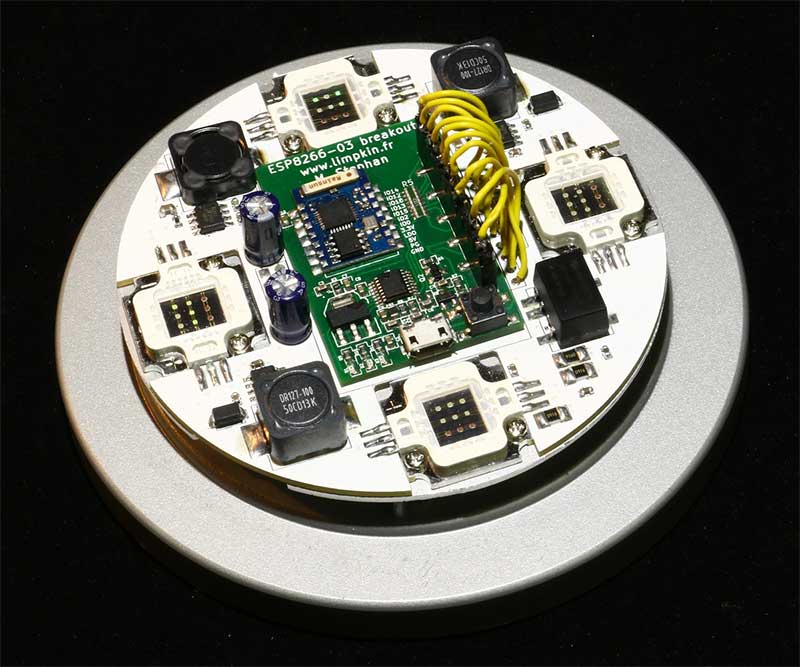
[Limpkin], aka Hackaday alum [Mathieu Stephan], is at it again, converting an IKEA lamp into a visual wake-up light. He wants to build an alarm that can be remotely triggered, He’s basing this project around a combination of an ESP8266 that handles the communication and timing, and a pile of 10-watt RGB LEDs. However, he is having a problem: every time he initializes the PWM (pulse width modulation) signalling that will control the level of the LEDs, his ESP8266 dev board reboots. So, he’s offering an interesting bounty for the person who finds the issue: figure it out and he will send you the lamp. Well, the PCB and components, anyway: you’ll have to add your own IKEA lamp. It’s an interesting approach to debugging a hardware problem, so feel free to take a look. The full hardware and software details are on his GitHub repository.
Debug An IKEA Lamp Hack, Win A Lamp Controller


I bet there’s something wrong with his code.
Or the hardware somewhere.
Or the wiring.
Anyway, I’m sure it’s one of those things.
:-)
If not, I bet there’s some grammar that’s wrong.
Most issues are power supply related with this SOC, been documented on http://www.esp8266.com a million times, other than that GPIO0,2,15 really need proper pullups or downs and the reset line needs to be firmly pulled up.
This was my first guess…. If you look at my other comments you will see that it isn’t the case.
Its a short for sure… Because he is made of aluminium!
Hint: alum != alumn … ;-)
Guess #1 is power supply noise / surge on PWM startup. My first trial would be to just disconnect the PWM lines before the LED drivers. If the reboot is still there it is a firmware issues as this eliminates the source of electrical noise.
If it does not reboot there are 2 paths to look at
#1 Power domain noise. Best to just hook up a scope to the module power rails and do a single trigger on a falling edge 10% below nominal. Look for spikes that may be tripping any BOR circuit that the ESP may be using.
#2 electrical noise coupling into sensitive nets. Got burnt in the past by a dev kit that had a VERY weak (~500k) pull up on the reset line. When a motor would turn on it generated enough noise to cause a valid reset pulse. Easiest way to track this one down is to just verify the reset pin has a proper strong pull to the proper value.
Unfortunately it’s a bit more complex than that. Pwm_init will work on esphttpd but not with cnlohr’s code… Which leads me to think it is code or makefile related. Commenting most of my code didn’t help either (in case it was a size problem).
Reset cause is wdt related.
What it says on reset? Usually ESP8266 gives a stack dump, time and cause of reset before rebooting
unhandled interrupt maybe?
I’m currently on holidays but I wrote it in the esp8266 thread…
From memory it is cause 1,6
Sounds like a typical brown-out scenario due to the lack of bulk capacitance. That breakout board looks like it is missing bulk capacitors on the output of the linear regulator. Try adding a 10uF or greater capacitor on the power rail feeding into the ESP8266.
I was thinking the same thing
This was my first thought as well. My second thought was that he had surely checked this already. But it never hurts to have a reminder of the obvious. I can’t count the number of times that I thought I killed a circuit, only to find that I simply forgot to plug it back in.
+1, definitely sounds like a brownout due to lack of capacitance and/or an inadequate supply
if not hardware, then i would guess a watchdog timer overflow is occurring during the PWM routine in firmware
Exactly!
Though I don’t know why that happens…
This is no doubt the answer. or even a combination of this an the answer above. maybe try adding a cap accross the regulator and also across the reset pin so that fluctuations in power do not reset nor cause low power
See my comment above. Adding a few extra capacitors or powering the board through USB doesn’t help
Can’t see the schematic, but it sound like a voltage droop – isolate the ESP8266’s power from the rest of the circuitry with a diode [say 1n4148] and a 100uf cap at the ESP8266′ power pins – that way, a brief dip in power will be isolated form the ESP8266 & not reset it.
Might want to go with a 1A schottky diode. 1N4148 is tiny signal diode and you shouldn’t try to use it at higher than the low tens of mA.
No flame intended, but 1N4148 is good for 100mA+, depending on mfg, but schottky would be better for less voltage drop.
Typ power of ESP2866 is over 200mA…
FYI 1N4148 forward drop is over 1.1V at your 100mA, so the last thing you want to fix in a case for voltage drop is more voltage drops.
This sounds like either code or hardware. I would personally go back to writing a very a basic program from scratch, no defines (lol at that thread conversation btw), super easy to read, to prove it isn’t my code. Verify it works, if it does, great, rewrite it or figure out what you did wrong. If it doesn’t suspect the hardware, bust out the scope, check the obvious, voltage drop, pwm signals, pin logic levels. This should all get you going in the right direction. Good luck!
Beautiful board btw, everything really. Let us all know how good the ring works as a heat sink, once it gets working.
“This sounds like either code or hardware”
well, that really narrows it down.
The ring works extremely well, though I had to lower the power as the hot air will stay inside the lamp…
I actually first started with esphttpd and it was working. Migrating to cnlohr’s code caused the problem.
Next in the list is indeed to use esphttp make file and move over cnlohr’s… Which may take a few days if not weeks
I had a similar issue with a TI launchpad and a Chinese constant current driver.
I believe (but I lack a scope to confirm) these drivers create a spike of emf noise on the pwm in line.
My solution was to put a 7400 series IC, either a non inverting octal buffer or transceiver, between the Mcu and the driver.
Odd thing is that with esphttpd the pwminit call works though…
What is the capacity of your power supply? It is quite possible that the LED’s are overloading it, and as it’s voltage is plummeting once the LEDs are using more amperage than it can keep up with. Depending on whether your 10W RGB leds are 3.3W+3.3W+3.3W (10W total) or 10W+10W+10W (30W total) you are talking either 40W or 120W, which translates into either 3.3A or 10A for the LED’s alone. Double or triple that to account for all the other things using power (and the fact that some power supplies “exagerate” their capabilities, etc.) and that circuit might need a 360W+ (continuous, not peak) 12V power supply.
And, don’t miss the good advice above to increase your decoupling capacitance. The inductors could quite easily be inducing some juicy spikes that could easily brownout your ESP8266.
You can check for these conditions by scoping the voltage both at the PSU (to see if it is being overpowered and dropping in voltage) and the ESP8266 to see if it is browning out. (And, of course, make sure that either your oscilloscope is rated for >>12V or use a voltage divider to prevent damage to your oscilloscope.)
Hello there!
Unfortunately the bug happens also when the LEDs are not connected…
Besides violating what the datasheet for the PDS1-S12-S5-M suggests for the input and output capacitance/choke, it also requires a minimum load current. Is this load requirement being followed? I’m not sure how much current an ESP8266 development module sinks.
Output load requirement
To ensure this module can operate efficiently and reliably, the minimum output load may not be less than 10% of the full load during operation. If the actual output power is low, connect a resistor at the output end in parallel to increase the load.
Also, verify that the 12 V power supply being used for the regulator is not dipping below 10.8~13.2 volts when the PWM is enabled.
Load requirement is followed. The bug when happens when the esp board is used as standalone.
Even*
1. I would place a 1k resistor between the EN-lines like in the datasheet of the led driver described.
2. Can’t ses where the timer functions are defined?!?!
CSInit();
CSPreInit();
CSTick();
Maybe this functions using the Hardware Timer… if that is true, the PWM API will not work anymore!
Excellent suggestion!
This is actually why I commented these lines during my tests and asked cnlohr about the hardware pwm… Didn’t help!
Driving LEDs in parallel is generally a bad idea – the hottest one will have the lowest Vf, and will draw the greatest current. Drive them in series instead – you wont need quite so much current, but you may need a boost rather than a buck.All the LEDs in each color will get the same current.
If a current sense resistor is needed, it can be small (looks like it should develop 0.2V at full current). With 1/3 the current (series connected LEDs), but 3 times the resistance, Psense is still 1/3 original power.
Make sure the current sources for each of the R, G, and B channels can provide full current with if the duty cycle gets stuck in the ON state, but not much more. That way, if the duty cycles get stuck in the ON state, you just burn power, not parts.Don’t worry about maintaining a particular color – this is to protect the circuit while maximizing output power and control range.
The capacitors in the LED driver outputs should connect from the top of the LEDs to ground, not across the LEDs – that defeats the purpose of current control. That Rsense also serves as a small ballast load.
The 12V supply should be able to carry the entire load with everything turned on 100% (just in case bits get stuck in the full-on state).
If the controller (ESP8266) gets reset (or worse, held in reset indefinitely) the circuit should go to a safe state (everything off).
The bug also happens when the LEDs are not connected.
After decreasing the Max power, I actually monitored the LEDs temperature when on… Max temperature reached was 60 degrees Celsius. I actually realised that I had forgotten about these pull downs!
Please note that anyone owning an esp8266 can check if this bug also happens in their setup by simply cloning the repository and running “make burn”
With any chance it is SDK related…
Please fix his first name spelling (see https://www.linkedin.com/in/mathieustephan).
Thanks :)
It will probably be the watchdog timer.
Add “yield()” into any loops or functions that prevent the controller from servicing the wifi.
The watchdog timer resets the whole device if it thinks it has got into a loop it cant get out of.
Any loop or function you call that takes you away from servicing the wifi for what it thinks is to long will cause the warchdog timer to reset the device.
The wait is very short so any function you add must take account of this.
Delay() has it built in but yield() can be used with no delay value.
When these are called it services the wifi and resets the counter on the watch dog.
Gordon
Excellent suggestion.
I however tried placing the pwm_init call at very different places inside the code and it didn’t make any difference. I also tried calling the delay function that supposedly also lets the system do its background tasks..
This is probably an obvious question, but have you tried commenting out the call to pwm_init and all the other pwm_* functions without changing anything else?
Of course :). I’ve spent days on this bug!
You’re too slow at kicking the dog.
Thought of that, inserted some delays and placed the pwminit call at other places… Didn’t help
Searching the internet, folk had problems with watchdog resets when using PWM.
https://github.com/esp8266/Arduino/issues/189
It’s conceivable that either the same library is being used, or your library and the arduino library are doing similar things. Either way, it’s a good chance that pwm_init itself is too slow. Moving it around therefore wouldn’t help. Also, my impression is that the pwm library is third party and simply dropped in. Maybe the working demo code has a less buggy version? Try stealing its pwm.h and pwm.c or whatever and using it in your project.
One last note, someone earlier mentioned a death rattle of sorts. It sounds like the esp will send out a stack trace when it resets. Have you looked into capturing that?
pwm.c is closed, libpwm.a is actually linked during compilation…
I never got a stack trace.
Sounds like too much current for the supply that runs the EsP8266. When the PWM kicks in, the power supply dips causing a reset of the ESP8266
See above… The call to pwminit works with the esphttpd project and trying other power supplies didn’t help.
try a different I/O pin – had issues with similar output stability using the shared pins. switching to a dedicated pin solved it.
Already tried setting only one pin with all the individual ios…. No dice
Have you tried a different ESP module or got other people to replicate the bug? What about ones from a different batch or one in a different package? The quality control of these things is not that great to non-existent.
Though as you say you’ve had other pwm software running fine I’d say it’s a makefile issue. The linking or producing of the binary is not happening correctly, the processor ends up doing something it shouldn’t and the watchdog timer trips.
My thinking exactly.
I was also hoping that people in the comments section would try on their esp8266 :)
I spent a day tweaking the make file parameters without success…
Are you able to “manually” PWM the pin using a loop? (same rate/frequency)
Yes
Maybe try bitbanging all your pwm channels at once? If there is a voltage droop, one pin might not be as bad as many pins all at once.
already tried :)
So, have you looked at the assembler code generated ?
I’d be willing to bet that compiler has generated invalid code that is causing a jump to vector 0, or simply casusing an invalid adress exception. The symptoms that it’s working embedded in other code is the tell tale sign of this.
If you can’t dissassemble the code, permuting some lines of code, or adding som additional lines of code close to the PWM call usually clears it up. Compiling with different optimisation flags might also work if it’s a bug in the code generation.
If the assembler code is correct, it’s likely that the state of the library/application issuing the PWM command is clobbering, or has been clobbered by some other call. A pain to track down obviously, but at least it seem to be easy to reproduce :)
Thanks for the disassembly suggestion!
I’ll try and do so when I’m back from holidays…
I’ve posted a long-ish reply on the esp forum but seems to be stuck in moderation.
Anyway for anyone stil looking for a solution, this is a bug in the SDK, there is an unaligned access to _Pri_3_HandlerAddress inside the NMI handler. The symbol may or may not end up aligned in RAM, depending on the linking order.
A linker-based workaround is as follows:
after:
_data_start = ABSOLUTE(.);
place the buggy symbol at a known aligned address:
_Pri_3_HandlerAddress = ABSOLUTE(.);
. = ABSOLUTE(4);
Do I win the lamp? :)
And here’s the whole story: http://www.esp8266.com/viewtopic.php?f=6&t=4675&start=48#p46002
of course!
Leave me your contact info at limpkin at limpkin dot fr
Cheers!