Old mainframe computers are interesting, especially to those of us who weren’t around to see them in action. We sit with old-timers and listen to their stories of the good ol’ days. They tell us about loading paper tape or giving instructions one at a time with toggle switches and LED output indicators. We hang on every word because its interesting to know how we got to this point in the tech-timeline and we appreciate the patience and insanity it must have taken to soldier on through the “good ol’ days”.
[Ken Shirriff] is making those good ol’ days come alive with a series of articles relating to his work with hardware at the Computer History Museum. His latest installment is an article describing the strange implementation of the IBM 1401’s qui-binary arithmetic. Full disclosure: It has not been confirmed that [Ken] is an “old-timer” however his article doesn’t help the argument that he isn’t.
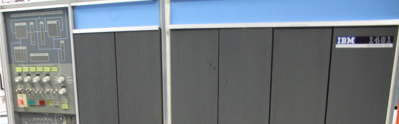
Ken describes in thorough detail how the IBM 1401 — which was first introduced in 1959 — takes a decimal number as an input and operates on it one BCD digit at a time. Before performing the instruction the BCD number is converted to qui-binary. Qui-binary is represented by 7 bits, 5 qui bits and 2 binary bits: 0000000. The qui portion represents the largest even number contained in the BCD value and the binary portion represents a 1 if the BCD value is odd or a 0 for even. For example if the BCD number is 9 then the Q8 bit and the B1 bit are set resulting in: 1000010.
The qui-binary representation makes for easy error checking since only one qui bit should be set and only one binary bit should be set. [Ken] goes on to explain more complex arithmetic and circuitry within the IBM 1401 in his post.
If you aren’t familiar with [Ken], we covered his reverse engineering of the Sinclair Scientific Calculator, his explanation of the TL431, and of course the core memory repair that is part of his Computer History Museum work.
Thanks for the tip [bobomb].


Okay, here’s a nit for me to pick: I don’t know for sure what kind of indicator lights the 1401 had; maybe they were incandescents, maybe they were neon, but they very certainly WEREN’T LEDs. The “old timers” flipping switches and reading LEDs are at least a decade later.
My first thought also.
Yes, the bulbs are incandescent (10V 10ES specifically). And they do burn out – I was recently single-stepping through an operation on the 1401 using the console switches and I was very confused by the computer’s results. After an embarrassingly long time, I realized the problem was simply a burnt-out bulb.
“I was recently single-stepping through an operation on the 1401…”
What is wrong with this statement?
I worked on them extensively from 1966-1979. Yes, they were incandescents, two thin wires emerging from a glass tubular enclosure that slid into a plastic holder – for replacement you tucked in the lamp, inserting the wires into tubular brass sockets, folding them over; then push in the ponty crimp connectors from the cable harness and you were done.
Raise up the lamp test switch to check it and you were done.
I think it was not Leds, but old light bulbs..
Incandescent and vacuum tube numerical displays on my old Burroughs in the 1970’s.
Almost certainly tiny incandescents, and probably operating at well below their rated voltage, so they’d didn’t need to be changed as often. That’d be particularly true of the ones that flashed on and off continuously.
Also never turned all the way off. Incandescents will last quite long if you keep them warm, just put a series resistor to preheat and short the resistor to turn the thing on.
Bulb lifetime is estimated to be dependant on the operating voltage with -13…-14th power. So if you decrease the operating voltage compared to the recommended by 20%, you get about 22 times longer lifetime. Another 20% down and there you are at 1000 times the normal lifetime. Well, theory says so…
I think the IBM 1620 used the same scheme. The logic circuits was on cards about 3X5 with diode transistor logic, pnp transistors so negative voltages. I replaced one with a Sphere base on a Motorola 6800. The connection to the Data Acquision system was implemented as a papertape device. BCD coding, and same negative logic so I use Opto isolators to conver the 6800 peripherial chips, 6821 i think, +5 to the DAS -7 (or was it -12) volt logic.
The 1620 used binary-coded-decimal as you mention, not the 1401’s bi-quinary, so it’s not “the same scheme”, although it did also calculate on one decimal digit at a time. The digits were actually 6 bits: 4 for the BCD, a parity bit, and a flag bit, which had several uses. The FORTRAN compiler could be set for anywhere from 2 to 28 digits of floating-point precision by use of a punch card at the beginning of the stack. That way you could do a quick (relatively speaking!) test run at low precision to check your logic, then rerun at higher precision to get your final results. The 1620 was my first (thanks to my high school math teacher, in 1965), and I learned machine language in an after-school class. Fond memories of all that!