New electrical components enable us to reconstruct old wiring more efficiently. Especially, the accessible and cheap FPGA kits which offer the possibility to put together wiring of many old computers as an “on-a-chip” solution.
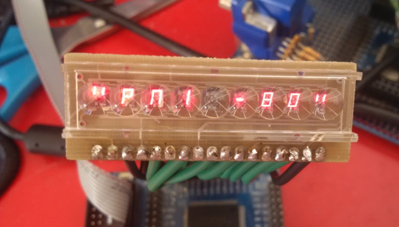
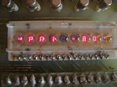
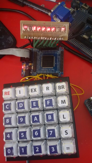
When I managed to get a hold of an old bubble LED display and a pretty mechanical matrix keyboard, I decided to build a replica of an old single board computer. Logical options seemed to be to build either KIM-1 or Heathkit ET-3400. Replicas of KIM-1 already exist, even for Arduino, so my task would be reduced to connect the keyboard and display. But then I told myself that I would use the fact that my bubble display has 9 positions as an excuse to build the legendary Czechoslovak Single Board Computer PMI-80 which used the same display. My replica is an FPGA, or rather an FPGA emulator of this very computer.
PMI-80
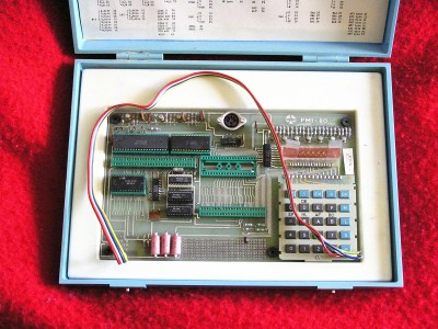
PMI-80 is a single board school computer based on an Intel 8080 processor. Since it was created in the eighties behind the so-called Iron Curtain, it used Czechoslovakian Tesla chips instead of original Intel ones, although they were functionally identical, including the numbering (Intel 8080A had a designation MHB8080A, PIO 8255A was sold as MHB8255A etc.)
The base consists of standard “Holy Trinity” wiring (8080A – 8224 – 8228). On the input of RESIN 8224 circuit was a capacitor and diode, providing reset after being powered on. The crystal had 10 MHz, so the computer was running at a frequency of 10/9 = 1.111 MHz. INTA input circuit 8228 was connected to +12V, which ensured that in the event of an interruption request, instruction RST 7 was executed (i.e. jump to the address $0038).
Memory was formed from 1K PROM (8608, 1kx8) and 1 kB RAM (2x 2114) chips. PROM was available at an address $0000 – $03FF, RAM was at $1C00 – $1FFF. It was even possible to add additional 2708 memory ($0400 – $07FF) to the board.
Programs were stored on tape in a very simple way, which was also controlled via the PIO 8255. Every entry had a start bit (1), then the actual value, and a stop bit (0). During recording a program generated a carrier frequency cycle of 0.2ms on PA6 port and strobbed it with the pin PA7. During reading the information was available at bit PC7.
PIO 8255 was connected as a peripheral at addresses $F8-$FB. The computer board allowed insertion of another PIO circuit, which was then connected to addresses $F4-$F7 and fully available to applications.
Operation
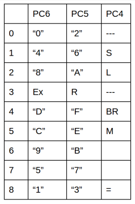 The keyboard was composed of 25 keys arranged in a 5×5 matrix. Inside, however, it was wired differently. Two keys (RE and I) have led directly to the inputs of the processor (RESET, respectively INT). The remaining keys (0-9, A-F, EX, R, BR, M, L, S and =) have been wired in the already mentioned 3×9 matrix as shown here.
After turning it on, the display screen read “PMI-80” and computer waited for any key press. After that it went into main screen mode, identified by “?” on the left side of the display. Then the computer waited for monitor commands.
Monitor commands
M – change / view the memory content. After pressing M the character M appears on the left and computer waits for address entry. Pressing = activates the data entry. Each time you press = the address pointer increases by 1. Data input is finished by pressing keys other than = and 0-F.
R – view and change the contents of registers. After pressing R the character “r” appears on the left and computer waits for a keystroke which corresponds to register pair (AF = A, B = BC, D = DE, HL 9 = 8 = SP). Again, it is possible to modify data and use = move to the next pair.
Ex – runs a program. Computer waits for an address, pressing = jumps into the program. The program can be terminated by jumping to the address 0 or address 8 (corresponds to jump to the monitor).
BR – same as G, but with a breakpoint. First you need to enter an address at which the program should be discontinued, and then the next starting address.
L, S – LOAD and SAVE data (not implemented here)
I – Interruption. Causes interruption and jumps to address $0038. There is only instruction: JMP $1FE6. At this address (in RAM), you must first create a jump into your handler routine.
RE – Reset. During reset the RAM does not clear, so it can be used as a program interruption and return to the monitor.
A Monitor listing with comments is available from the Git repository.
PMI-80 in FPGA
 I chose an inexpensive FPGA dev kit, EP2C5/EP2C6 Mini Board, which is the same one Grant Searle used for his Multicomp (Thanks for the inspiration!). It has an Altera Cyclone II chip which I programmed using VHDL.
I connected a keyboard as a 5×5 matrix, not in an original 3×9; recoding into a form suitable for the PMI is being handled inside the FPGA.
The display is connected through resistors straight to the FPGA, and again, all logic and remapping into a form suitable for emulation is being done inside the FPGA.
An interface for working with a tape recorder is missing, I did not implement this yet. You can see my current implementation at my Github repo.
I used a freeware VHDL implementation of the 8080 called Light8080. It is not “T-perfect”, but that was not required anyway. I have also used a pia8255 component.
The main code is in the file rmi.vhd, where all the “glue logic” for each component: 8080, 8255, RAM, ROM, keyboard and LED.
The archive also includes test components that I used when working on the emulation, eg. a simple display showing hexadecimal numbers. Getting the emulation to work correctly was somewhat precarious. The original implementation of the 8080 processor worked with slightly non-standard timing, therefore strange states appeared on the bus, for example, RAM stopped giving out information before the processor managed to read it, etc. A few things helped me:
- Test ROM with a simple code
- Clock generator with a frequency of about 1 Hz
- Hexadecimal display (component automatically refreshes the display content, I brought data into the input directly from data or address bus)
- Altera Probe – virtual logic probe connected to a circuit, it transmits data over a JTAG interface to the Quartus IDE.


Building the hardware and writing the emulator was a weekend of work and it’s still a “version 0.1”. In the future I would like to extend the system to emulate other single-board computers (KIM, ET, perhaps COSMAC ELF) and emulate the tape, perhaps as RS-232 interface. Take a look at the quick video demo. Check out the resources below, and leave a comment if you’re interested in more retro-computing on a chip projects.
Resources
Source codes: https://github.com/maly/fpmi
PMI-80 description in slovak:
http://www.nostalcomp.cz/pdfka/pmi80_popis.pdf
http://www.nostalcomp.cz/pdfka/pmi80_doplnky.pdf
http://www.nostalcomp.cz/pdfka/pmi_prirucka1.pdf
http://www.nostalcomp.cz/pdfka/pmi_prirucka2.pdf


+1 for mentioning Brian
I don’t even have the PMI-80 anymore. It’s at the office, in the small museum we’re building.
Kde jste sehnal ten roztomilý displejíček?
Třeba (značně) starší kalkulačky OKU z produkce Tesly…display drží v napružených kontaktech, takže jde rovnou vyndat, nic se nemusí pájet…Jinak byl standartně dodávan s PMI-80…
Typy třeba – CQYP 95 (SSSR verze) nebo NSA 1198 či VQD30, občas se vyskytují na Aukru.
Hello, how are you?
Není to pravda, je displej CQYP95 z polské výroby o Unitra CEMI závodu ;) Pozdrav!
sorry for offtopic, but where you get that nice transparent-white buttons??! :)
They look like the same kind of keys you’d find on a Cash Register, so you can put your own printed codes underneath.
The keyboard is available on eBay: https://www.ebay.com/itm/1pc-White-Keyboard-5×5-25-keys-Metal-Panel-SPST-Machine-type-Pushbutton-Switch-/130541363513
Technology rapidly changing. 10-15 years ago nobody can’t image iPad, thin notebooks or soft led displays (example http://hannoufmediagroup.com/portfolio-item/hmg-soft-led-module-display/).