Recently I’ve been learning more about classic analog music synthesizers and sequencers. This has led me to the Baby10, a classic and simple analog sequencer design. In this article I’ll introduce its basic operation, and the builds of some awesome hackers based on this design.
Sequencers produce, a sequence of varying voltages. These control voltages (CV) can then be use to control other components. Often this is a simple tone generator. While the concept is simple, it can produce awesome results:
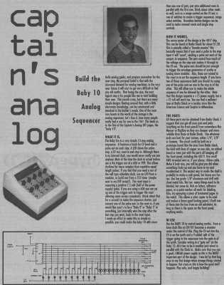
A basic sequencer is a great beginners project. It’s easy to understand the basic operation of the circuit and produces a satisfyingly entertaining result. The Baby 10 was originally published in a column called “Captain’s Analog”, but has now been widely shared online.
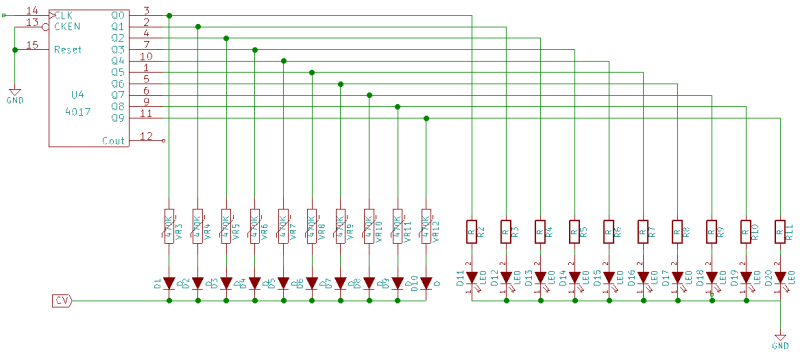
The circuit uses the 4017, a simple CMOS decade counter. The 4017 takes an input clock signal then sequentially outputs a high pulse on each of 10 output pins. As such, the 4017 does almost everything we need from a sequencer in a single IC! However, we want our sequencer to output a varying voltage which we can then use to generate differing tones.
To accomplish this variable resistors are connected to each of the output pins. A diode in series with the variable resistor stops the outputs fighting against each other (in layman’s terms).
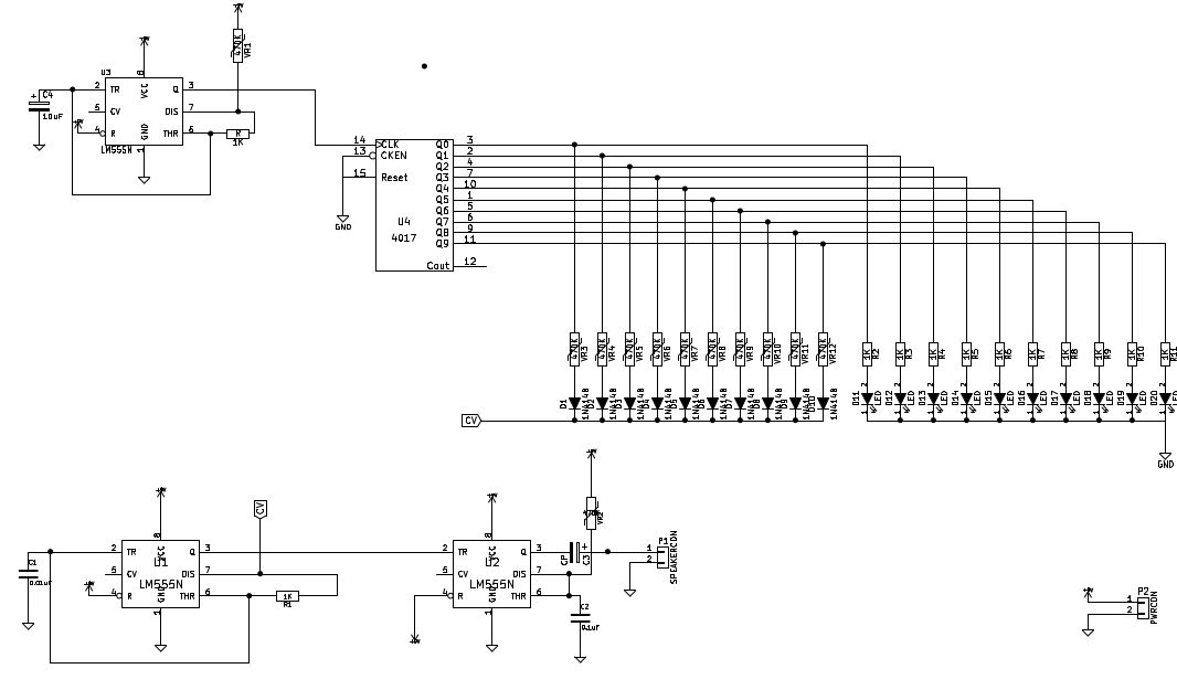
To make the sequencer more visually attractive (and give some feedback) LEDs are often also added to the output of the 4017. A complete Baby 10 sequencer is shown in the schematic below. The original circuit used 1N917s, these are no longer available but the part has been replaced by the 1N4148.
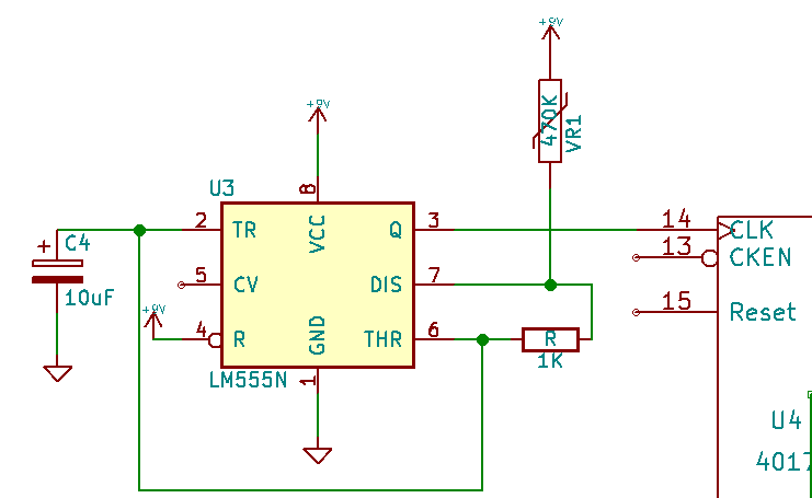
While this completes the basic sequencer a couple of other components are required to produce a system that actually does something useful. We’ll need a clock input to drive the sequencer, and something to generate tones on the output. For both of these purposes we can use the ubiquitous 555!
For the clock we can use a simple 555 astable oscillator. The schematic below should produce a clock with a suitably variable range (from about 70Hz to 0.3Hz). This is about right for an audible range, but if you’re interested in changing this there are some great 555 value calculators which make the process easy.
Now the sequencer is sending out clocked, varying control voltages they need to be turned into a tone to produce a sound. Many commercial synths provide a CV input. The basic sequencer is therefore already useful:
But if you’re building your system from scratch you’ll need to add a tone generator yourself. You could use another 555 astable oscillator (using the same circuit as the clock but changing the values). But a common choice is to use an astable and monostable 555 as an Atari punk console (we have a detailed article on the punk console which describes how it works).
The complete Baby10/Atarti punk console circuit, then looks something like this:
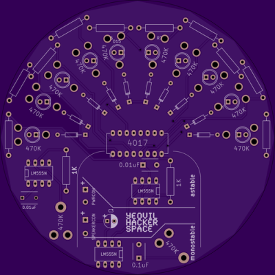
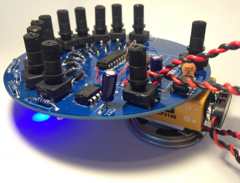
It’s pretty easy to put this project together on a breadboard, and the components only cost a few dollars. But I’m also hoping to put a PCB together so we can run workshops at our local hacker space (if you’d like the gerbers, comment below!).
The 4017 driving the Baby10 step limits the sequencer to 10 steps. For most musical applications however 10 steps sounds distinctly odd, By looping one of the outputs to the reset pin you can limit the number of steps. Most hackers choose to use the Baby10 as an 8 step sequencer (Baby8), but there’s lots of scope in varying the number of steps.
Using the Baby10 as a basis you can hack around with the design in various ways to produce more interesting sounds, and many hackers have produced unique sequencers based on this design. By combining 2 4017s for example you can build a 16 step sequencer:
If you want to get more ambitious, you can combine multiple Baby8s (or multiple Baby16s if you feel like it!) to produce interesting effects:
There are many other possibilities too, such as using an irregular clock input, chaining multiple sequencers together, and experimenting with different synths. All this experimentation makes the Baby10 a fun project which can start of simple and get progressively more complicated — it has inspired me to build my own kit version of the design. Hopefully it’s also simple enough that beginners can grasp basic concepts and learn something from the project too. If you want to dig into more of the core concepts of the synth, check out [Elliot Williams’] Logic Noise series. In particular, he covers the 4017, and it was the Baby10 that inspired that post. In any case, working with these designs you should end up with something that produces entertaining and unique music.


Neat
I’ll take those gerbers, please!
Hey Alex, I’m revising them today to fix a couple of bodges and will post later. As there’s been some interest I’m also going selling them as kits: https://www.whitefordresearch.com/products/punkseq10-preorder
I’ve updated the gerbers, you can find them on by blog here: http://41j.com/blog/2016/01/punkseq10-r2/
Hi Nava,
I have built a couple of baby10s over the years and was glad to see the article here on HaD. I took a look at your site and wanted to say I will definitely be ordering a kit. Thanks for being a reasonable human being with the pricing! You have set it at a great level for the hobbyist on up :) Keep up the interesting posts (loved the blog nudge about sticky tape article) and keep up the tinkering!
Very cool, the beginning of the first video sounds like Defender sound effects!
Very nice! Pre ordered a kit!
After I built my first Atari Punk Console with a 556, the 4017 was the second chip I played with. I set it up as an 8 step sequencer powering LEDs on wire stalks. I used it to control a dual FM synth with photoresistors controlling the pitch. By carefully adjusting the distances from the sensors and the individual stalks, it produced musical patterns. This was one of my first real musical projects, and it’s still going strong all these years later.
The medusatron-
https://vimeo.com/59045912
Those old VCR channel setting pot banks should be of a great use in this project. I have saved several of them mostly 14’s but I know of one with 16 positions. They have the high accuracy needed to tune musically and are compact. Pocket sized sequencer! You can pop them apart and cut the common trace to use in this design. IIRC they are 100K.
Stars End
Saturday night Sunday 1 AM EST (06:00 GMT) 5 hours of such sequencer driven goodness on WXPN at a 128k stream. Since the mid 70’s this program has featured the deep German School of electronic music. Live performances on air by many well known synth artists.
Oh man the vcr channel setting pot! I used to tune in the adult cable channels that way when I was a kid. Albeit they were b/w and sometimes negative images and the vertical hold that didn’t haha. Don’t judge-it was long ago and pre-computer ownage for my family haha. I had forgotten all about that-thanks :)
Will check out Stars End-sounds right up my alley.
The first video seems to have a lot of buzz but the others aren’t nearly as pronounced. Why is that? Is it because of the veroboard?
The buzzing in the first one got to me eventually so I had to move on to the other videos.
Hey does anyone know why the second video doesn’t have the diodes on the circuit? This is really confusing. I didn’t have any so I patched without them and I don’t think it is working. My CV is only between a few mV and about 1.3V. Does anyone have this working that could give me what their CV out from the sequencer looks like? Thanks!
Hello hackaday friends,
Here are my engineering notes after completing this project. The main schematic infers ground and power. The potentiometer must go to ground and power. Now, connect the middle pin to the 4017 chip to complete the path. Ground and power through out Nava’s diagram are assumed. Normally, this is standard but there are 2 ways you can hook up a knob like this and you need to compare the diagrams to get the whole picture. Zoom in on the original baby ten circuit and this is more obvious. The diodes are a key feature for the CV.
Also, wikipedia has a alternate 555 punk atari circuit diagram that gives you another knob, if you’re feeling creative.
I encourage folks to hook up 2 steps then route the 3rd one to reset to confirm the circuit is wired correctly on the first go around. This makes hooking the next 8 up to go quickly; they use all the same series of parts.
When you get to placing the knobs in order for your PCB board, notice the decade counter fires the pins off in a non-sequential pattern. The 4017 datasheet is really helpful here.
Thank you for writing the post! That was a week of evenings well spent.
Really nice article, but I have one question: Where do I have to attach the CV on an Atari Punk Console build of an NE556 timer?
Hi I wired up this circuit and I dont get any sound. All i hear is a soft metrome sound. I directly connected a 8ohm speaker to the output. Is this the problem?
How can I obtain the gerber files?
This article is very nice, and I made my own board of the APC, see in this video: https://www.youtube.com/watch?v=Rjkp3HMDDiY&feature=youtu.be
Nice article, would you mind telling me what capacitors, resistors and diodes you are using as well as the Potentiometer ratings?
Thanks
Hi!! I buld one incorporating a 4046 based osc, but works ina very weird way, will need to sit and check it out… I’m really interestef in knowing how could I “attach” 2 4017 in order to make a 16 step seq!! How is that connection made?? Would it be possible to manually select between 1×16 steps and 2×8?? That would be really awesome!
I am also wanting to cascade two CD4017 counters, using the Yeovil hacker space boards I had made for my own use, my thought is to stack two boards and wire only the CD4017 and it’s diodes and pots up to the control voltage of the main board, will this work, or will I need another solution like and gates?