
In this session of Logic Noise, we’ll combine a bunch of the modules we’ve made so far into an autonomous machine noise box. OK, at least we’ll start to sequence some of these sounds.
A sequencer is at the heart of any drum box and the centerpiece of any “serious” modular synthesizer. Why? Because you just can’t tweak all those knobs and play notes and dance around at the same time. Or at least we can’t. So you gotta automate. Previously we did it with switches. This time we do it with logic pulses.
The 4017 Decade Counter
The featured chip this session, the one that gets it all done, is the 4017 Decade Counter. It’s a strange chip, left over from the days when people wanted to count things using IC logic chips instead of just running the input into a microcontroller. But therein lies its charm and usability.
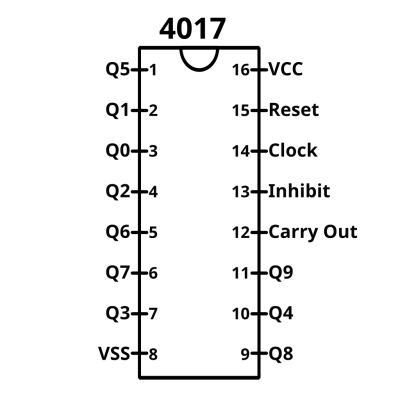
At its simplest, you input a clock signal and one of ten different outputs (Q0-Q9) is set high while the others are all low. On the next rising edge of the clock, the next output is set high and the previous is set low. This goes on until the count loops around the end.
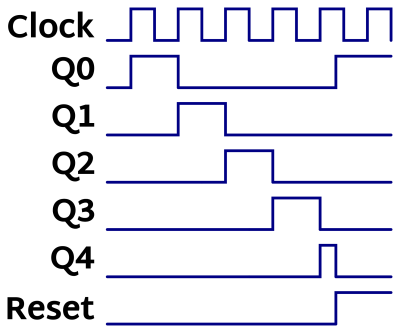
One feature that makes the 4017 super useful is the reset pin. When a high voltage is set on reset, the first output (Q0) is set high and all the others zeroed out — the chip starts counting at zero again. The cool trick here is that you can connect the reset pin up to one of the Q outputs and the counter will automatically reset once it reaches that output. If reset is connected to Q2, for example, the count will go Q0 then Q1, and then immediately reset back to Q0 again: Q0, Q1, Q0, Q1… If you wanted an octal (divide by eight) counter, you just hook the reset pin up to Q8.
Eight steps is pretty standard (boring?) and you can get nice groove patterns by selecting odd sequence lengths. But if you want your standard drum machine, hooking the reset up to Q8 is the way to go.
Looking at the timing diagram, notice that the reset pin can also be used asynchronously. That is, the chip will reset as soon as the reset line goes high — it doesn’t wait to finish the current clock cycle. Here, for instance, we hit reset while clock step five (on Q4) was still active.
Async reset means that your reset source can come from outside the 4017 chip and its counter. For instance, you could connect the reset line through a pushbutton to VCC and reset the sequence at will. (If you do this, consider a pulldown resistor on the reset line to keep the voltage level well-defined when the button isn’t pressed.)
There are two more pins left over. The “Carry Out” pin is low when Q0-Q4 is high and high when Q5-Q9 are high. When the chip is counting up to ten, this produces a nice square wave with a cycle once for every ten counts. As the name suggests, this can be fed into another 4017’s clock input and you’ll have a count-to-100 device. Chain up the next carry out to a third 4017, and you can count up to 1,000 clock pulses. (Tie all the reset lines together to zero them at once, if you’re actually counting.) Carry out is less useful for us, but we’ll play around with it a tiny bit next session anyway.
Finally, there’s the “Inhibit” pin. In most implementations of the 4017 chips, setting inhibit high makes the chip ignore the incoming clock pulses. Some manufacturers’ chips have some slightly more clever logic where the inhibit line can be dual-purposed to count up for high-to-low transitions if the “clock” line is held low and the “inhibit” line toggled. We’ll not be using this feature, so just remember to tie the inhibit line (pin 13) to ground so that it’s not glitching around.
Back to what matters here. We’ve got a chip that’ll put out logic voltage signals on one pin after the other, clockable and resettable. That’s the heart of a simple sequencer. Most of what we’ll be doing this session is making these voltage steps play well with our quick-and-dirty CMOS logic synth modules.
The Basic Sequencer
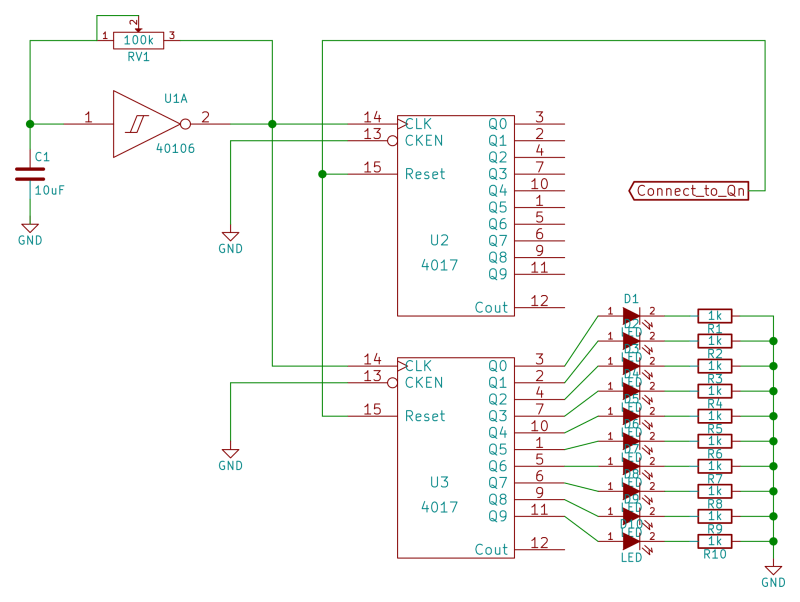
The sequencer that we’ll be building up this session is nothing more than a 4017 clocked by a 40106-based oscillator that’s running at a “tempo” frequency rather than at audio rates. Indeed, you could stop there. But for the low, low price of another 4017 logic chip, some LEDs and resistors, you can have something deluxe.
Our version of this simple sequencer is going to be built from two 4017s with the clock and reset lines in common between them. This means that the two 4017’s will run in lockstep with one another at all times. We can use one 4017 for driving our synth devices and the other for driving ten status LEDs, without having to worry about the LEDs pulling the output voltages low if they draw too much current.
Of course, if you don’t want the LEDs, you can entirely omit the second 4017 from the circuit. Or if you’re feeling lucky, you could hang the LEDs off of the signal outputs directly. But since we’ll be already demanding a little bit more current from the 4017s than they’re designed for, we think it’s easily worth the extra chip for insurance and convenience. Plus, it makes for a lot cleaner layout on the breadboard.
Gating Oscillators with the 4017 Sequencer
The first thing you’d probably like to do with the sequencer is to play a bunch of notes. The quick-and-dirtiest way to do that with our current setup is to construct one oscillator per note you’d like to play and then have that oscillator sound only when the corresponding “Q” output of the 4017 is set high. That should be easy enough, and it is.
If you remember back from our first session, we used a diode to create a hard-sync oscillator sound by gating one oscillator with another. The oscillators all work by charging up a capacitor through the feedback resistor, recall, so if you can drain enough current out to prevent the capacitor from charging up, you can silence the oscillator.
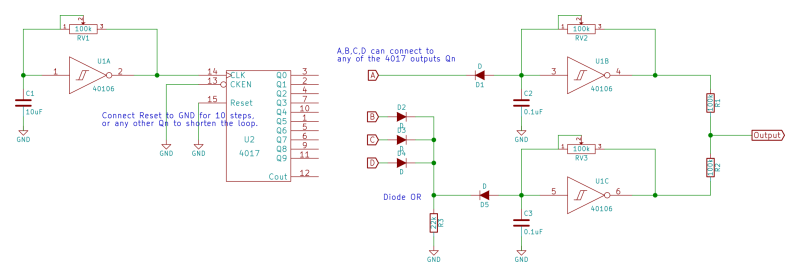
First look at the single audio oscillator on the top right, connected to the 4017 through input “A”. When the corresponding 4017 output is low, whatever current passes through the feedback resistor (RV2) to charge up the capacitor (C2) will get sucked out the diode (D1) into the 4017, and the oscillator won’t oscillate. When the 4017’s output is high, the diode blocks and the oscillator is free to do its thing. Easy and done.
The Diode OR Gate
But what if we want one note to fire multiple times? Here’s an interfacing trick that can be handy, called “Mickey-mouse” logic or less imaginatively, diode logic. The idea is that you can set up the desired default logic state with a pull-up or pull-down resistor, and then override it with signals coming in through a bunch of diodes. To add more inputs to the OR all you have to do is add more diodes to the circuit, which makes it useful when you need something odd like a seven-way OR function.
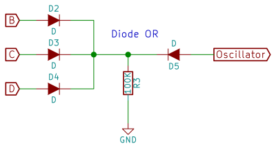 Consider inputs B, C, and D in this snippet from our full schematic. When none of B, C, or D are high voltage, none of the diodes (D2-D4) will be conducting, and the pulldown resistor (R3) will set the voltage going into diode D5 low, pulling current out of the oscillator and stopping it from working. When any of B, C, or D are logic high the 4017 will pass current through the corresponding diode and out to the junction with the resistor. When this point is high, the diode D5 won’t conduct and the oscillator runs, just as in the single-step version above it.
Why the diodes D2-D4? If one stage of the 4017 is high, say B, the other two must be low. Without the diodes in the circuit, we’d be shorting the two pins of the 4017 together, and all bets are off about the voltage at the junction labelled “Diode OR”. These diodes keep one pin of the 4017 from fighting with another.
Picking the value for the resistor in the diode OR circuit is a little critical. It needs have a low enough resistance that it can pull down the oscillator circuit. So R3 needs to be less than the value we’ve got dialed in on the variable resistor that tunes the oscillator (RV3). But R3 needs to be large enough that when the 4017 pushes its high voltage through the output diodes, the voltage at the junction rises enough to block diode D5.
The 4017 is only specified for an input or output drive current of three milliamps with a 10V supply, and only one milliamp at 5V, which means that we should use a pulldown resistor no smaller than 2.2K as a pulldown if we want a voltage higher than VCC/2 at the diode OR’s junction. Use something even larger helps reduce the demand for current on the 4017.
Indeed, it’s this requirement for the 4017 to source a bunch of current that motivates using a second 4017 to handle the LEDs. Our 4017 datasheets only specifies three milliamps of output drive or sink current connected to a 10V supply. (And this drops to one milliamp at 5V VCC.) With 1K resistors on the LEDs, we’re probably already drawing five to ten milliamps — way more than the chip is specified for. Adding more load to a single 4017 chip to drive the diode OR, or even more outputs, is asking for trouble. You could imagine buffering each output of the 4017, but at some point it’s just easier to toss another 4017 into the design.
Anyway, technical details aside, that handles controlling individual oscillators from the sequencer. And we’ve seen how to run one oscillator from multiple sequencer stages. With six oscillator per 40106 chip, you should be able to make reasonable melodies with a minimum of parts.
Gate-to-Trigger Pulse Circuit
Now it’s time to drive our percussion. If you remember the two-diode VCA from our Cowbell session, we actually built out a “gate to trigger” converter. In modular synth lingo, a “gate” signal is a logic signal that stays high as long as (for instance) a key is pressed, and then drops back down low instantly when it’s released. The 4017’s individual outputs look a lot like a gate signal — each output is high during its complete step and only during its step. Or cymbal’s decaying amplitude circuit, on the other hand, needed a quick pulse at the start of the step, called a “trigger” signal.
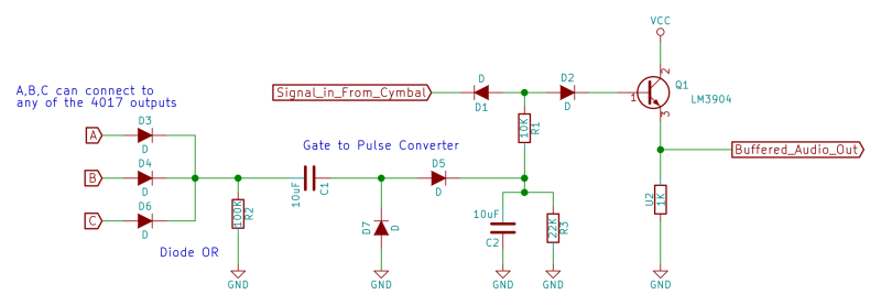
At the heart of the gate-to-trigger circuit is a capacitor (C1). Changes in voltage on one side of the capacitor let a bit of current through until the capacitor has charged up enough to resist further current. This turns the leading and trailing edges of our gate signal into positive and negative spike pulses.
We choose to only pass the positive voltage spike by using a diode (D5). The remaining problem, that we glossed over in the Cowbell session, is that the negative spike doesn’t pass through D5. In fact, without the diode pointing up from ground (D7) in the circuit, the right-hand plate of the capacitor C1 would get stuck at a negative voltage with respect to ground. Additional positive pulses sent through from the 4017 on the left-hand side would maybe raise the voltage up as high as zero volts, but certainly wouldn’t be enough to pass through diode D5 and make a sound. In short, you’d have one hit and then you’d never hear it again.
The diode up from ground (D7) prevents this situation by charging the right-hand side of C1 up to at least a diode-drop less than 0V after each negative spike. This makes the gate to pulse circuit work a little bit like a pump; when charge is pushed through the capacitor from the 4017 side, it passes through D5, and when charge is pulled back the other way it is sourced through the D7 “check valve” from ground.
If you buy that analogy, the rest of the cymbals interface circuit should be clear. A diode OR on the left-hand side allows multiple cymbal hits. Again, the choice of the pulldown resistor is important, but here there is a lot less demand for it to be tiny. The resistor R2 is only responsible for discharging the left-hand side of capacitor C1 between hits. If you’re running fast sequences, experiment with lower values.
Variable Trigger Pulse for the Twin-T Drum
Again, for the bass drum sound, we’re going to need a gate-to-trigger circuit, and aside from using a smaller capacitor than the one above, it’s just the same. But one thing we really like about twin-t drum circuits is the volume dynamics across different input voltage spikes. That is, if you hit the twin-t with a small voltage spike it’s quiet, and if you hit it with a large voltage spike it gets loud. Adding in this kind of variation into your drum patterns make them sound less robotic, so it’s worth thinking about and spending a couple of resistors on. And indeed, that’s all that we’ll need.
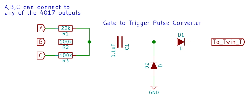
This circuit combines the outputs from the 4017 in an effective voltage divider. Since only one of the 4017’s outputs will be high at any given time, we can figure this out pretty quickly. When A goes high, there’s a voltage divider to ground formed by the 22K resistor R1 and the two 100K resistors in parallel, R2 and R3, for 50K. The voltage output at the junction of the resistors is 22 / 72 * VCC, or about 2.75V with a 9V supply.
When either of B or C is high, the effective resistor to ground has the parallel resistance of 22K and 100K resistors, or 18K. The resulting voltage spike has a peak around 1.4V, so it sounds a bit quieter. All of these pulses have to pass through the diode D1 as well, so they’re probably attenuated even further. You can just play around with the values until they sound right.
Output Mixer and Final Details
Finally, all of the various sound sources are combined simply by passing them through 100K resistors and connecting them together at the amplifier’s input. This simple summing “mixer” is quick and dirty and works just fine. If you want one sound source quieter or louder, you can change these resistor values within reason: how much you can get away with depends on the input impedance of the amplifier you’ve got it hooked into. Factors of two are probably OK. Experiment.
A more engineered solution involves removing the DC offset from each sound source and summing them (probably with variable gain) using operational amplifiers or similar. That’s a great idea, but that’s also another project in itself.
Inspiration
The classic 4017-based sequencer is the “Baby 10“. The original was intended to drive voltage-controlled analog gear, so it put out an adjustable voltage with each step in addition to the on-off gate signals that we’re using. If you’ve got anything that’ll take control voltages, it’s easily worth the ten potentiometers to build out a full Baby 10. You’ll find tons of links on the web.
Next Session
This session was all about sequencing for control. Next session we’ll go back to crazy. We’ll continue to use the 4017, although next time in “unexpected” ways. But the main attraction is going to be a shift register, specifically the 4015. Mayhem ensues!


Great article once again. Crystal clear and always inspiring. bravo
Great series. Going from bottom up, from simple circuits to more complex devices, I like it.
Maybe I’m just being lazy but would it be possible to include a parts list with these posts? I’m going to use this as my first foray into really building electronics and going through each post and digging out what exactly I need is a bit difficult. It’s not impossible but typing in potentiometer into Digi-Key and trying to figure out what would work is a little overwhelming. The obvious power supply, breadboard, jumper wires etc… are easy enough but figuring out what potentiometers, diodes, resistors, and capacitors to have on hand is where it gets tricky.
Anyway thanks for the great posts and I’m looking forward to trying to build all of this stuff!
Build your own partslists.. It will take about 5 minutes per post…The nature of this series dictates this approach, IMO.
When preparing for such project, it is good to get extra different values of things like potentiometers and resistors or capacitors. They cost pennies.
Just making the parts list will help you tackle the rest of the project.
I totally agree with you. Taking the time to figure out the materials needed and the procedure is a great way to prepare for something like this. As well as having extras and variants for parts either as a precaution or for experimentation.
For me at least a parts list would help me make sure I’m in the same ballpark especially for things I’m uncertain about. Even an informal list of something like ‘You’ll need a couple of these and a few of these’ would be helpful.
That being said after rereading and studying diagrams I have a much better idea of what I need to get.
Hey there,
If you start with the CD40106 – I’ve made a table which shows the frequency range depending on the potentiometer and capacitor values (only a few do really make sense). With linear 100k potentiometers and 100nF capacitors you get a nice tone range. I’ve read that when it comes to diodes you mostly need 1N4148 and 1N4007. https://hackaday.io/project/5237-zynthia-sequencer-synthesizer/log/16838-hardware-vs-frequency
Thanks! Your table is super helpful as well as your project! Between what you just said and rereading everything I think I’ll be able to start ordering stuff! I really appreciate it! Exclamation mark!
4017 step sequencer was one of my first ‘real’ projects.. This is a great series.
One cool thing is that you can add MIDI sync to this sequencer with the addition of a component or two – http://www.blacet.com/MSfig4.gif – this being an ‘advanced’ version of the method.
GREAT article – proving why electronics magazines from dead trees are obsolete.
Hey there! Im doing a circuit bending course at uni and im using this as a guidline for a project im doing. Im having a bit of trouble with getting the 40106 chip to play multiple notes from the 4017. I have 6 inverters running from the 40106 so i have 6 independent synths running with pots connected, exactly as it appears in the tutorial. Each independent synth is connected to a corresponding count from the 4017 and is working fine on their own, however my problem arises when i try to send all the outputs from the 40106 and mix them. I just get a clicking sound but no bleeps coming through? Any assistance would be amazing as ive tried trouble shooting and i cant find information anywhere else!
Thanks
hey there,
i tried to hook more than three gate-inputs to the 2diode vca (i got it working, by the way) so i could play like each count a cymbal. after five it goes very quit and at a certain point you don’t here the extra inputs anymore. how does it come, and is there a solution? may be an opamp? but that is against the idea of logic noise, unless i use 4069, right?
this is great stuff, however, I am looking for a chip that works with a 555 timer that will sequence as follows: 1on, 2on, 3on, 4on, ……….10on, all off, repeat. what have you got???