I have an old Prusa i2 that, like an old car, has been getting some major part replacements lately after many many hours of service. Recently both the extruder and the extruder motor died. The extruder died of brass fill filament sintering to the inside of the nozzle (always flush your extruder of exotic filaments). The motor died at the wires of constant flexing. Regardless, I replaced the motors and found myself with an issue; the new motor and hotend (junk motor from the junk bin, and an E3D v6, which is fantastic) worked way better and was pushing out too much filament.
The hotend, driver gear, extruder mechanics, back pressure, motor, and plastic type all work together to set how much plastic you can push through the nozzle at once. Even the speed at which the plastic is going through the nozzle can change how much friction that plastic experiences. Most of these effects are somewhat negligible. The printer does, however, have a sort of baseline steps per mm of plastic you can set.
The goal is to have a steps per mm that is exactly matched to how much plastic the printer pushes out. If you say 10mm, 10mm of filament should be eaten by the extruder. This setting is the “steps per mm” in the firmware configuration. This number should be close to perfect. Once it is, you can tune it by setting the “extrusion multiplier” setting in most slicers when you switch materials, or have environmental differences to compensate for.
The problem comes in measuring the filament that is extruded. Filament comes off a spool and is pulled through an imprecisely held nozzle in an imprecisely made extruder assembly. On top of all that, the filament twists and curves. This makes it difficult to hold against a ruler or caliper and get a trustworthy measurement.
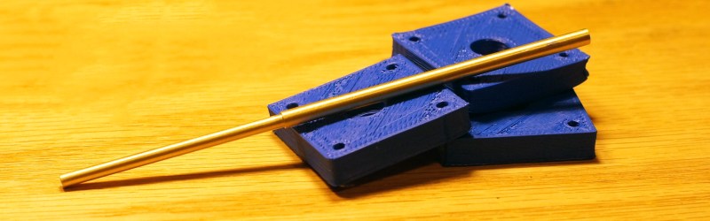
I have come up with a little measuring device you can make with some brass tubing, sandpaper, a saw (or pipe cutter), a pencil torch, solder, and some calipers. To start with, find two pieces of tubing. The first’s ID must fit closely with the filament size you use. The second tube must allow the inside tubing to slide inside of it closely. A close fit is essential.
Building a Filament Calibration Tool


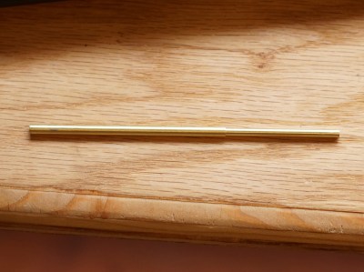
Cut a 75mm and 25mm section from the small tube. Cut a 75mm section from the large tube. I recommend cutting a larger section than needed and filing/sanding down to get the exact measurements. A lot of precision isn’t necessary for this tool to work, but it’s satisfying to practice your 19th century fitting skills to get precision out of low tech tools.
Next braze the 25mm section of the small tube and the 75mm section of the large tube. (If you don’t have a pencil torch or aggressive soldering iron, super glue will work just fine for this part.) I used the other small tube and some kapton tape to hold the little tube in place for brazing. This won’t take a lot of solder to do, if you over do it you may accidentally braze the whole assembly together.
After the brazing is complete, hit the assembly with some sandpaper and Scotch-Brite to polish it up and bring it into final tolerance. For me I wanted it to be 100mm long.
Now slide the 75mm small tube in the combined 75mm and 25mm tube. The device is complete. I have a model of the measuring tool on Fusion 360.
Measuring the Steps of the Filament


Our tool is going to make it simple to use a digital caliper to measure the exact length of filament our extruder is using. That’s because measuring the metal tubing from the end of the large tube to the end of the small one is perfect for calipers while measuring a flexible plastic strand is not.
To measure the steps per mm of the filament break off a half meter and heat the printer’s extruder up. Make sure this is the filament you will be using most. For me it is the blue PLA from UltiMachine. Next, slide the tool on the filament until the small end touches the part where the filament enters the extruder assembly.
Extend the tool an arbitrary distance that’s more than 10mm. Mark the filament carefully with a marker. Then make sure the tool is firmly against the extruder and just touching the marked line. Hold the tool at the sliding joint and take it off the filament. Do not let the length of the tool change. Measure the tool’s length with a caliper and press zero on your caliper.
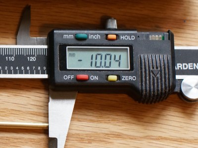
Next, slide the tool back onto the filament and extrude 10-20mm of filament. Once again, slide the large tube up to the line you marked previously and then (holding the joint secure) pull it off the filament, and measure the tool again. The negative length displayed on your calipers is the length extruded through the nozzle.
Once you have this value we can move to the next step, which is adjusting the steps per mm in your printer firmware.
Adjust the Steps per Millimeter Based on This Measurement
Open up your firmware, find the section where you set your steps per mm and write it down. Take the length of filament you expected to be dispensed and divide it by the actual filament extruded (the number on your caliper). Multiply this by the steps per mm setting you wrote down. This gives you your new steps per mm. Replace the old steps per mm with the newly calculated one and upload the firmware.
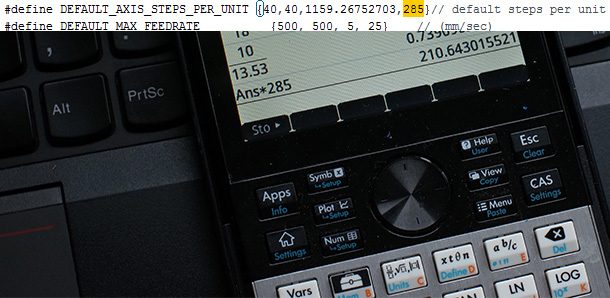
In my case I asked the printer to extrude 10mm of filament but using my new tool I measured 13.53mm actually extruded. My printer firmware has a steps per mm setting of 285. Here is the equation I used:

From this I know that I have indeed been over-extruding (by about 26%!). My new extruder step setting needs to be 211 steps.
Just to be sure, repeat the measurement covered in the previous steps and see if you get 10mm when you ask for 10mm. I had to repeat the process one more time to make up for, presumably, not keeping the tool from sliding before measuring it, but in the end I got a nearly perfect 1:1 ratio.
So we know that despite careful measurement, filament extrusion varies based on many factors, and you can ‘sorta’ tune this by eye. Why go through all the trouble of making this tool and getting it super exact? When it comes to tuning any machine, you want to eliminate as many unknowns as possible and then tune the remaining. The best unknowns are the ones you can measure. For a printer the first place to start is the mechanics. I make sure everything is oiled and tight. Then I use a dial indicator to make sure my steps per mm are exact, my bed is level, and that I’m not losing steps (by doing the same move back and forth 10 or 20 times and then seeing if the position on the indicator is the same). Next I check that the reported temperature of my hotend is the one that is actually there. I use cheap NIST traceable thermocouple thermometer for this.
Now, I can add the steps per mm of the extruder. Previously one would vaguely calculate the expected steps per mm based on the gear and stepper, then tune from there. Or one would hold a ruler up to the filament and try that way. Now that I have it set exactly, I KNOW that this value is correct and I don’t have to change it. I am now free to tune the other values in my slicer and get a better print.
In this case, knowing that my steps per mm was exact led me to discover that the extrusion width I had set in my slicer, simplify3d, was off by .08 and that my new E3D nozzle produced a more exact extrusion width than I expected. Also, embarrassingly, that my x-axis pulley was broken. Once I adjusted for that and fixed the pulley; my prints look great!
What do you think? Was there an easier way to get this measurement without making a tool? I’d love to hear about it in the comment section!


bras tubing -> brass tubing
So and underwire bra is really an undertube bra?
B^)
Here’s my solution to the same problem: http://www.thingiverse.com/thing:535273
It’s a bowden extruder caliper mount.
I should add, this is specifically designed to be screwed onto my kossel bowden extruder, but I’ve included the OpenSCAD source on thingiverse, so it’s super easy to change the mount point to support any printer.
Maaan, that addition ruined the punch line.
the i2 is not a bad design, but not a good design either. The biggest improvement I made on my i2 was to replace those triangles on the side with some lasercut wood. Next was the use nylock nuts or jam nuts on every piece of the frame.
then replace the y axis motor mount with something stronger. Then replace the Z-X mounts with better ends (see the mendel90 ends, that now clamp down on the rods). Then replace the 8mm z leadscrew with a 6mm one. After all that, the machine was rock solid and making fantastic prints (until it caught on fire from a poorly designed electronics board).
Also, 10mm is not enough for a good calibration, I personally calibrate over 100mm lengths, 50mm minimum. a 1mm difference over 100mm may not sound like a lot, but it’s 1%, which can be the difference between gaps and a rough surface on your print, or near perfect prints.
You got me thinking about a similar mechanism, but with a hollowed screw. The screw would hold it’s position better (and you could add a jam nut). you could even add a caliper-like mechanism (or drive the screw with a servo or other high precision movement) to contain the entire measurement in one device.
And don’t use the extrusion multiplier to account for filament changes, use the filament diameter, accurately measured over several points and orientations. the multiplier, once set, shouldn’t need to be changed.
+1 for measuring over a greater length for much lower error.
I got tired of horsing around with adjustments to my RepRap, so I bought a scrapped Stratasys and got it running. I run it lights out and don’t worry about it failing catastrophically or burning down my house.
Do you have to use the Stratasys filament or did you hack around that?
It’s pretty easy to get around that. Hackaday did a post on it a bit over a year ago. Sometime after that, somebody cracked the encryption and now you can buy programmers on ebay. I built one myself with parts I had laying around, so now I use polystyrene as a support material and various ABS as my normal print material. I haven’t even had to mess around with the tip temperatures yet. I’m planning to try Nylon this week sometime.
Seriously , there is a much easier, old-school way of doing this. Simply cut a straw at 98mm. Use the straw to measure a 100mm extrusion. When the filament is flush with the end, your at 100mm. Making the straw 98mm compensates for the slight bending of the filament in the straw.
aaah, stop using digital calipers for precise measurements! Bad bad bad! If it doesn’t have teeth, it’s not counting perfectly every time.
I agree with you, but I can take my calipers and measure something and the same measurement twice. It’s true, the cheap chinese calipers like I have are pretty bad. They change accuracy when the battery is low. They aren’t temperature compensated. However, they’re fairly serviceable for the price. I’d like a Mitutoyo Digimatic Absolute IP67, which fixes all the problems with the digital calipers. I like digital due to the lack of parallax errors and a bit less fragility.
I disagree my Mitutoyo digital calipers give accurate and very repeatable measurements.
Keyword: Mitutoyo. I’d trust measuring with a Mitutoyo-made banana over an eBay digital caliper.
Really? Thats a silly notion. You do understand that he isnt measuring to any real accuracy here right? Most digitals (even cheap ones) are very capable of .001″ repeatability , hence why almost none do tenths. Digitals are more than adequate for this job, as well as many other precision measurements, if you are using them as a caliper should be. Walk in to any modern machine shop and see if they arent using digital for O.D. measurements in at least the .005″ range , which is standard tolerance. If your trying to measure ten-thousandths , sure a dial caliper will get you closer , but your talking tolerances most machine shops wont hold unless its a ground part. Some of the crap people come up with.
“I use cheap NIST traceable thermocouple thermometer for this.”
I’d like to measure the temps of my hotend/heated bed with some reasonable precision. I don’t have anything to calibrate my tools with, though. Where do I get one of these NIST thermo-whatsits?
I have one like this: http://www.amazon.com/Thomas-Traceable-Workhorse-Thermometer-Thermocouple/dp/B006H8MJ8K/ Mine was cole-parmer branded and came with a little certificate. I got another thermocouple for it http://www.amazon.com/Milwaukee-49-77-2002-Thermocouple-K-Type/dp/B003V8BF2U/ That works a bit better for point measurements up to a range. It’s really handy.
I’d try to find a small inner tube that’s threaded on the outside, so that you can use a nut to hold the outer tube in place instead of trying to keep it from sliding with your fingers.
I went an even cheaper route:
I used my calipers to measure 30mm up from the hole where the filament enters the extruder.
I placed a piece of electrical tape at that point to mark it, then extruded 20mm and measure where the tape is at.
In my case, it was 8.9mm, which means 21.1mm of filament was extruded instead of 20. I had my numbers ready to adjust the filament feed-rate.
just place the tape where ever, its not important as long as you have a before and after measurement. Math does the rest.
Where are you buying the brass tubing from, and what are the inner and outer diameters that are being used? Love the idea, it’s simple and would work well on my direct drive extruder. Thanks for the idea!
Any hobby rc shop, most hardware stores will carry it. I don’t know the measurements exactly. They are in the 360 model linked. I took a length of filament with me to the store and tried it until I got a tube that fit. Then I took the tube that fit and tried it on larger tubes until I got a good slide fit.
I would think that using a spring loaded rubberwheel based measurement device with an encoder attached to that wheel could work pretty well too. This could probably be mounted somewhere between the filament spool and extruder in a fixed position, so you could always do a quick check with every type of filament you have loaded in your printer. I don’t think the filament could slip very much on a rubber wheel, since the speeds are pretty low and the wheel can basically be designed to turn freely with almost zero friction. The encoder would not have to be anything complicated or extremely precise since you could just base the measurement on one or more full revolutions of the wheel.
That would probably be the road i tried to go down if i ever wanted to have some higher precision, but for now, i just observe roughly how much filament gets pulled in the extruder with a mark on the filament.
A permanently attached part that electronically measures something and expects the user to report the measurement back to it’s own controler? Once you go that route why not connect it directly to your electronics and modify your firmware to calibrate itself and constantly update it’s own steps per mm?
In this case it might be good then to add a little calibration blob to the begining of every print.
Maybe you could add a max change factor too. If it’s suddenly reading mm per step that is unrealistically far from it’s previous value something is wrong. (probably slipping). Keep using the old value and give the user some kind of feedback.