There’s no denying the retro appeal of the warm glow of a set of Nixies, and when a friend was looking for a unique touch for the case of his new liquid-cooled PC, [Luca] pitched in with this sweet Nixie thermometer.
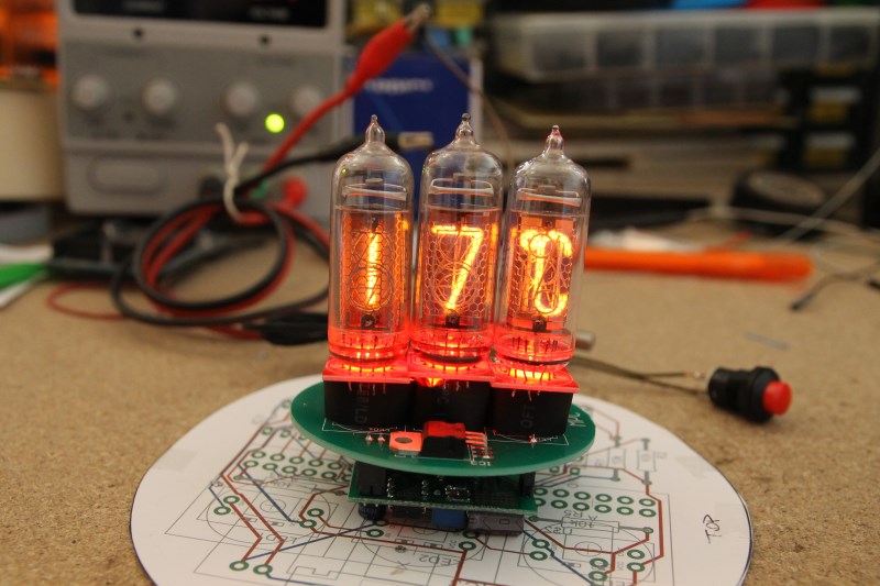
From the look of [Luca]’s detailed blog entries, he’s been at this build since the New Year. He starts with a list of requirements, including the oddly specific need for a round PC board. For the thermometer, three Nixies are enlisted for the display, two for the temperature and one for the units. Everything was prototyped on perf board before committing to a PCB design, but even with careful planning, the Nixie sockets on the final PCB came out a tiny bit too close together. Luckily the tubes still fit, even if they are snuggled together some. And yes, the tube bases all include the hated RGB LEDs – hey, it’s what the customer wanted. The specs are for the colors to change at the touch of a button; we’d like to see a color gradient linked to the temperature – blue for “nice and cool”, red for “leave the room.” You can see the finished thermometer in action below the break.
The recent run of Nixie projects continues unabated, and this one has a nice look that’s sure to complement the finished case. We’ve asked [Luca] to keep us up-to-date on the project, so hopefully we’ll get a look at why a round PCB is needed. While we wait for that, check out an earlier Nixie thermometer build with a bar graph twist.


Cool, but that kerning…
http://xkcd.com/1015/
LOL! :)
Everything is better with nixies!
Bad kerning is called keming.
+1
Funny how a display device once so roundly hated has become so loved.
I don’t know anyone that ever hated nixies. They were priced off the market when red LED’s hit the catalogs, both due to the cost of the devices themselves, as well as the cost of the support (HV drivers, power supply, tube-type sockets, etc), but they stayed in some higher end equipment much longer than one might have expected.
They were disliked in the days before LEDs were available. They were unloved by those that used commercial test equipment that they were in for a number of reasons.
I also do not understand this. They look quite nice, but not nicer than various other display types. And the voltage requirements make them just not easy to use.
I’m happy to see a successfully planned and executed project, and looking forward to the packaged result. But I’m a little alarmed by the PCB layout, which looks autorouted without much concern for isolating the 200V anode supply from the low-voltage logic. From the narrow traces and lack of heatsinking on the 7812, I imagine it isn’t expected to source a lot of current. For a version 2, maybe a smaller 78L12 could be subsituted and positioned on the Pro Mini side of the board, leaving the opposing side devoted to the HV connections with lots of isolation between traces.
I also see there are also no input or output capacitors near the regulator, and no decoupling caps at the ICs. At least a small external capacitance is strongly recommended for stable operation of 78xx regulators; details in the datasheet. 0.1uF and 10uF caps could be added in parallel with input and output to ground by soldering straight to the regulator pads, using the current layout as-is.
Maybe you should design your own version a make Hackaday.io project out of it.
OK, fine:
http://hackaday.com/2014/01/16/retro-modern-nixie-clock/
Not on Hackaday.io, but I did include the design files.
Current project, round PCB even:
http://reboots.g-cipher.net/cd72front.jpg
http://reboots.g-cipher.net/cd72rear.jpg
Wow, delivared.
Nice work too.
Sweet
That’s awesome work.
I’m looking for more info on the design of the 170 – 200V supply for these tubes. Does anyone have links / design info on these?
I would not consider this to be just useless nitpicking. Should anyone attempt to recreate the build, the advice is very sound. 78xx regulators may actually misbehave (oscillate) without an output cap, by when, without an oscilloscope, you might wonder what is actually happening there. 200V DC from a charged cap is also a potential risk – it might not kill, but would definitely be very unpleasant to touch. Routing HV simply has to be taken seriously.
This project would be well outside my abilities, but I think if I were to do it, I would choose the Burroughs 8422 or B-5991 style tubes (or the Russian equivalent in size and style) or the completely round style with the head-on display instead of looking through the side of the tube. Then you could mount the display in a standard 5.25″ drive bay.
I’m not exactly sure how Luca plans to mount the display, but my only guesses would be on top of the case or inside it facing a window in the case’s side panels. I’d be really interested to see the final product, or at least an explanation of how it is to be used and what kind of case it is made for.
I did this with Russian IN-17 Nixies for a 3.5″ drive bay for a friend back in college. That was back when desktops always had parallel ports, but USB printers were becoming the norm, so it ran off the parallel port. Unfortunately I don’t think I have any pictures.
very nice. Everything is better with nixies!