The 555 can do anything. OK, that’s become a bit of a trope in our community, but there is quite a lot of truth behind it: this little timer chip is an astonishingly versatile component.
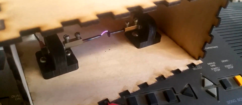
[Alexander Lang] has added another achievement to the 555’s repertoire, he’s used one in the creation of a plasma speaker. Working at Hackspace Manchester, he’s used the 555 as a pulse-width modulator that drives a flyback transformer through a MOSFET, which feeds a spark gap mounted in a lasercut enclosure. The results maybe aren’t yet hi-fi, but it works, and is very audible.
We’ve been following this project for a while, as he’s updated his progress through several iterations. From initial design idea through PCB and enclosure design, to a first working prototype and some audio refinements, and finally this latest post with the spark gap in its enclosure. He is still refining his speaker, so there is more to come
In the video below the break he demonstrates his pulse width modulator, and tests the device using a keyboard as an input.
https://www.youtube.com/watch?v=pQg9PdutBvc
We’ve only featured one plasma speaker here at Hackaday, but we’ve certainly covered a host of 555 projects. Some are particularly memorable, like this 555-based computer, while others like this AM transmitter and receiver are more fun projects. Browse them yourself, by looking at posts tagged “555”.
Meanwhile in 2012 we noted the passing of its creator, [Hans Camenzind], to whom we 555-heads owe so much.


Clever!
Though, every ham operator within 100 miles is going to hate your guts.
Does it really put out a signal that powerful though?
I’ve heard people over 1000km transmitting 300mW SSB on HF. So you don’t need a strong signal to be heard if the conditions are right.
The thing with this device is that the signal will be dirty and very broadband, and will be changing a lot. So lots of potential to upset people.
Just don’t run the flyback transformer higher than 1 Mhz and lower than 110 Khz.
I won’t matter what the drive frequency is. He is driving with a square wave, and tremendous amounts of harmonic / sub-harmonic noise are produced.
It doesn’t matter what wave type or frequency you use to drive an arc because the arc itself is white noise and broadband from DC to GOD frequencies.
Electric arcs are rich in high frequency noise by themselves, not to mention the addition of harmonics of the drive frequency as Mark mentioned.
The arc won’t generate “from DC to GOD.” The arc is white noise, but so what? It’s being modulated by a square wave. So convolve white noise with said square wave, and you’ll get the emitted frequencies, which will be primarily high frequency.
(Obviously can’t be DC because DC would imply that the arc is essentially ‘on’ forever.)
@[Pat]
Some points –
Flyback transformers have a built in voltage multiplier and diode because they are made for TV tubes which are essentially big valves and run on DC.
Lets look at the effects of your inter-modulation on – say – the 400MHz band – modulated by 20kHz
you get 400.000020MHz and 399.99980MHz – hmmm not big different there given that most IF stages are 455kHz wide.
I didn’t read the article to see what drive frequency he is using as flyback transformers (LOPT) are designed for 15 – 16 kHz. If he is using a much higher frequency then it would still pale by comparison to the bandwidth of noise anyway. We’re not talking about modulating a fixed carrier frequency here … it’s wideband noise to start with.
Can you see that you can see it? I mean you can see it can’t you? So you do understand that the noise output is sooooo wide that it even covers the visible spectrum and then extends even further in UV and beyond. ie nano-meter frequencies.
Yes, the emission extends to very *high* frequencies, but not very *low* frequencies. It obviously doesn’t extend to DC.
I regularly talk to people on 5 watts 900 to 1200 miles away. My longest contact on 2.5 watts was 1500 miles. Most hams, at least the ones that know what they are doing use very very low power to communicate very long distances.
I’m going to test the RF output and provide some clarity. It believe it won’t be as bad as perceived. The signal is very broadband though so we will have to see. I don’t intend using the plasma speaker permanently. It was just for the ‘craic’ – for the fun of it.
I though that operating a Spark-gap transmitter was illegal to use nowadays in almost all countries ?
It is. Although he would argue that he did not specifically add an antenna to it for the purpose of wireless transmission, the enclosure provides no EMI shielding, nor are the electronics or cabling shielded.
Hi, I’m Alex the lad who designed the above plasma speaker. A spark Gap transmitter is illegal, but that wasn’t my primary intention and that is what I would argue when and if I was challenged I actually don’t intend using this circuit permanently…It was purely for fun and educational purposes. I have access to a screened room and an open area test site equivalent in the form of a GTEM cell. Just for the information I will measure the amount of RF the plasma speaker gives off and provide some results. It isn’t actually as bad as some make out. As has also been mentioned if I were to encase the electronics and shorten the high voltage connection leads to the flyback transformer and apply ferrite sleeves the amount of EMI should reduce considerably.
I’m not entirely convinced, having spent most of my life as a radio amateur on the same property as someone doing a lot of arc welding. Yes, there is QRM, but as long as it’s not coupled through a tuned circuit to an antenna then it’s probably a lot better than you’d expect.
I agree. I have heard static on my receiver when my neighbor is arc welding (or using his plasma torch), which I assume the FCC would deem “interference” even though It does not disrupt my usage of the receiver. I have never heard of the FCC prosecuting someone for using an arc welder.
Most arc Welders are DC, not high frequency modulated.
It doesn’t matter. The electrical noise comes from the photonic emission and last I checked that produces a very wide range of white noise.
And in any case it has no antenna or SWR circuit so it can only cause RF disturbances at a short range.
Not entirely correct. The older generation of machines used large variable transformers and banks of capacitors and other components to generate a DC output, while the newer generation of machines are inverter based and use high frequency DC-DC converters to generate Dc, AC or the high frequency AC that various TIG setups make good use of, or as seen AC plasma torches. Their shielding is usually pretty minimal if any, but in the environment of a shop which is typically filled with all sorts of things spewing out RF noise, it’s not a big deal. Worst case you’ll notice in a shop running old TIG machines with HF start and other old accessories is it might overwhelm the radio at your work station with static for a second as it starts, and maybe if the radio shares a ground with the welder you might get a bit of noise and static, but even though they generate a lot of electrical noise and are poorly shielded and other negative aspects, they really need to be very close to something to swamp it, if you’re running a noisy inverter on the other side of even a small shop from the radio, you’ll likely never notice the radio having issues.
TIG machines and some plasma cutters use a little spark gap oscillator to create the HV that is induced on the work circuit for arc starting. They will cause brief radio interference when they fire.
Also newer inverter welders can cause interference if their lid is off. I was working on a Miller XMT-304 and every time I turned it on with the cover off my cd player would stop playing 20 feet away. Turn it off and it would resume playing from where it left off. Damnedest thing…
Hey, does anyone care to explain what the purpose of the transistor configuration with 1 npn and 1 pnp in his circuit is used for? I have seen many other plasma speakers that drive the MOSFET directly from the 555 like this: http://people.cornellcollege.edu/dsherman/plasma-speaker-circuit.pdf
What are the advantages of using the method that was used in the article vs. the method I linked to?
The circuit he is using allows faster turn-on of the main mosfet. The output of the 555 can’t source much current, or swing to the 12v rail, so driving the gate capacitance of the FET is challenging for the 555.
He is using the 7555 which is a low power version of the 555 and probably can’t drive the FET directly and this explains one transistor but not the other. A simple load resistor should have been enough to bias the FET back off.
Maybe he has a little Irish in him “to be sure … to be sure” lol (no offense intended) as the second transistor will “surely” bias the FET back off – simple solution – no calculator needed. It also avoids any linear region and hence no “she canna take no more captain” moments.
Also using a different FET changes things. The so called Digital FETs are what … IRF or IRFZ
Thanks RÖB!
Hi Rob – Alex here…you are quite correct! The 555 did not drive the Fet directly well so I added the long tail pair. I do have Irish ancestry and yes I do like to be sure! I could probably have used a resistor and driven the FET directly…To be honest I didn’t really think the output stage through properly. Thank you for commenting
Are there any reasons why a spark inside a wooden box might not be the best idea?
I can’t say it is the absolute best, but it is certainly among one of the best materials to use.
It won’t conduct current during a fault and hurt equipment/you/others like metals.
It takes a significantly longer time to warm up at any one spot to burst into flames like paper or fabrics.
It won’t melt and release toxic fumes within seconds like many plastics.
It isn’t fragile in and of itself like glass, which is annoying to work with at least and turns into a dangerous situation on its own when broken by other means.
Acrylic may be a better option, as perhaps fiberglass, but both are more expensive as a material and harder and more expensive to work with.
Certain plastics can be made to be very heat resistant, but too are much more expensive.
What material would you suggest that would be about as affordable as the common materials above, simple to work with at home, yet not actually be more dangerous to use than wood?
A wood wire-mesh ceramic (left over tiles from the last remodeling project) sandwich ? May not improve the sound, but the tiles won’t burn and the wire mesh could make a (crude) Faraday cage …
I respectfully disagree that wood is “certainly among one of the best materials to use” for the application of an enclosure for an open spark (flame).
Acrylic feels only slightly better than wood from a fire safety perspective. Both provide fuel to the fire and have fairly low ignition points.
Not sure we can just dictate that it be as “affordable as the common materials you list while also being simple to work with at home, yet not actually be more dangerous to use than wood”. We are essentially trying to contain fire here. That said, glass is an electrical insulator as well as being fairly easy to work with and does not support combustion. It, as you mentioned, can break. It could be laminated or reinforced to help mitigate this. Cutting glass in complicated patterns is tricky and generally requires special equipment. Metals can be cut and welded or bent and bolted together.
Even an inner lining of metal could help improve things. PTFE or silicone based chemistry sheets could work. Brick or other ceramics feel like they would work well. Calcium silicate or millboard sheets. Mineralwool. Maybe scavenge an old oven or portable fireplace as a starting point?
I agree. A coffee can would be cheap and effective, and provide some EMI shielding. If you are worried about getting shocked put foam around the can and earth ground the can.
A fish tank would be better – that won’t catch fire!. Just make some miniature Faraday cages for the little fishies and give them miniature LASERs.
It looks like he is running it from 12 Volts so the spark would be under 2kV – like a car spark plug really.
Hi, I’m Alex the lad who made the plasma speaker. I chose wood because It’s non conductive, can be laser cut and can be finished well to make things more attractive. In use the arc from the plasma speaker gives off a lot of heat…more than I anticipated! I estimate that the surface temperature of the wood is at 75 degrees Celsius directly above the arc…I think that a plastic case would possibly melt of crack at those sort of temperatures where as the wood does not care in the slightest. I didn’t really choose wood based on it’s material properties however it was a material that I could use in a laser cutter…As other people have mentioned there are plenty of materials that could have been used that may or may not be an improvement.
I will take a look at this. I had not really put any thought into using a lacquer which would improve sound quality. Hearing is believing though and if the lacquer is not too expensive I will try it. Thanks for commenting – Alex
What if I told you there is a 556
That terrible background noise is probably generated by that plasma field right on top of your keyboard electronics.
Yikes, that keyboard’s panel is subject to that HV mayhem right on top. Goes right into the chip with the most magic smoke inside. Though that wood is a fair insulator it is ringed with carbon resistors from the ugly burnt-by-laser crenelated joints. Get some plastic sheeting and form and put the gap inside at the throat of a horn to up the volume. Cover the rear entrance for safe operation. Making a “morning glory” horn with laser cutouts is easy in plastic, it bends to a nice curve.
You could do it with a 555! No, wait…
Awesome work with the speaker, looking forward to more!
All the ozone from the corona does wonders for the lungs and various other materials in the room too.
I have a high voltage, high frequency generator here used for insulation testing that will produce 6 inch corona arcs into the air when its on and it will totally jack up the other three guys computers in the room. But all that wide band noise is low in power when spread out across the spectrum. it doesn;t do much harm beyond the walls of the room. Filtered into frequencies of interest and/or amplified, it could do some harm probably.
Which MOSFET are you using. In the first schematic, you use IRF240, however you provide the datasheet for the IRF250. In your second schematic, you use IRF251.
Hi Steel_9 apologies for the confusion. I used several mosfets over the course of the development of the circuit. Any high power N-type mosfet will probably work. My first choice is the IRFP250 as I found this one to work well. The others all also worked. I have also used an IRF540 and and an IRF840. All working reasonably well. The issue is with ensuring that the FET can handle high current in normal operation with a heatsink and be able to survive the very high voltage flyback noise which is in the order of 500 to 800 volts. This is why I am now looking to add a varistor and some other supression components across the Drain and source of the FET to make the circuit more robust.
use a transorb. varistors degrade over time.
A fair comment…I have no experience in selecting transorbs but that’s something new to learn. Really all I’m looking to do is to protect the FET from the inductive spikes coming from the flyback transformer. I was hoping that the diode would protect it enough but that has not been the case. The amount of energy in the pulse (when I viewed them on an oscilloscope) was much more than anticipated. I’ve been through several FETS because it.
Part of the heat is unavoidable as it the result of the internal diode (or zenner) dissipating the energy of the back EMF (flyback noise) as heat.
The other possible part of the heating could be (testing needed to quantify) the FET operation in a linear mode near the edges of it’s transitions. Your totem pole drive will cancel most but not all of this as FETs have a highly capacities gate – the equivalent to Cbe in a transistor. Your totem pole drive also has a band gap due to the additions of two Vbe’s.
Transistors however will turn off faster and therefore minimize the linear regions near transitions and reduce heat dissipation to a minimum.
I would suggest a BU508D as it has a very high collector voltage, a built in flyback diode, and a built in resistor to bleed off the Cbe that has been calculated by the manufacturer you would need to loose the totem pole output and use a simple drive transistor / load resistor. The BU508D was commonly used in flyback circuits to you will find some schematics in google.
A common solutions was to use a transformer to drive the flyback. Also the flytback *ALLWAYS* had a heatsink.
Please note that you specifically need the “D” version as other versions like the “A” has no diode or bleed resistor.
Our local science museum used to demonstrate such a thing and they got a VERY nasty ‘cease and desist’ letter from the local Police dept one block away because it jammed their UHF radios.