In any motorsport, the more you know about how the engine is performing, the better a driver is likely to do in a race. That holds for bicycles, too, where the driver just happens to also be the engine. There are plenty of cheap bike computers on the market, but the high-end meters that measure power output are a bit pricey. [chiprobot] is looking to change that with a home-brew, low-cost bike power meter.
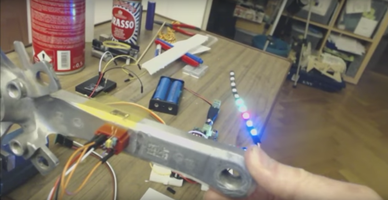
The project still appears to be in the proof-of-concept phase, but it’s an interesting concept for sure. The stock crank arms are carefully fitted with two pairs of tiny strain gauges. The gauges are wired in a Wheatstone bridge arrangement, with one gauge in each pair mounted perpendicular to the force on the crank to serve as a static reference. Output from the bridge is fed to an HX711 instrumentation amplifier. The demo video below shows how sensitive the bridge and 24-bit amp are.
The goal is to send crank data to a handlebar-mounted UI via WiFi with a pair of ESP8266 modules. We like the idea of a bicycle area network, but [chiprobot] has his work cut out for him in terms of ruggedizing and weatherproofing all this gear. We’ll be sure to keep an eye on this project. In the meantime, there’s plenty to learn from this bike power meter project we covered last year.


He also has Di2-like concept test on his channel for you bikers out there.
I wanna try this out…
Why do you need esp8266?
I’m guessing so there wont be a connecting wire between the crank and handle bar? Such a wire could get tangled with the rotation? Another plus or minus depending on your politics is you can send the data off into the cloud to be analysed etc.
Just because the big commercial spy companies are pushing the cloud concept a lot it does not necessarily mean you can’t do you own thing, you can set up your own server (or rent one) and make your own cloud type of hub, using any encryption you deem secure, or none at all and rely on it being independent to keep it safe from advertisers at least.
Don’t be suckered into thinking the goolges and amazons and microsofts are all there is. Even if they hope to make it so one day, after they bought all the politicians and got everybody fooled into yet another TTIP and ‘cyber security’ bill until no freedom is left.
Could have dropped any MCU in there, so it doesn’t need an esp8266. I’m using them at the moment where I don’t need many pins and would have used a Arduino
Ok, but how do you connect the crank to the handle bar which has the UI? The rotation of the crank would probably pull the UI from the handle bar or snap the connecting wire.
Take your pick – it also depends what you are trying to do, you may just want to record the data for later analysis.
Plenty of wireless option through without the esp8266. Many wireless modules outside of the 2.4Ghz spectrum that would work if you are creating the head unit as well. There are also BLE modules if you want to connect to phones etc….
If you want a wired option you would need to look into connector/slip rings – https://en.wikipedia.org/wiki/Slip_ring. May be worth while just to get the power to the crank.
Thanks for the slip ring information. Yea you are right any wireless tech would work.
I wonder if you could use the intermittent short touch of a single piece of metal touching it once every rotation to power it, I mean if the power requirements are low a pulse should be able to slowly charge enough to keep things going.
I am talking theoretical when you want to do it that way for various reasons like low cost and reduced complexity and such.
Alternatively for power, they sell bicycle lights that work by passing near a magnet, so that idea is also an option, coil and magnet and you have no-contact low power.
Yo° squeeks,
The system still needed a wireless link in my case which is why I plumped for the ESP8266 with its WiFi plus processor , so no extra MCU’s were needed.
I choose the ESP8266 as the power meter strain gauges and amplifier are mounted on the crank-arm/pedal of the bike , as you cant use wires to do this it has to Transmitted by some form of RF.
The ESP8266 has a low profile and small form factor , great for mounting on the crank.
It is shielded (metal can) , so one less interference source to forget.
The ESP8266 is an all in one chip, no need to add extra MCU’s. keeps hardware light and simple on the crank.
Its easy to program via the Arduino IDE…. which is where I found a library for controlling the HX711 instrumentation amplifier.
…. hence my choice of WiFi
The builder has a long way to go before this particular build is calibrated, practical & weatherproof, but it’s a great introduction to using strain gauges, which have a lot of applications.
Yo° Thinkerer,
Yes indeed I need an ingenious way of applying a 25-50Kgm weight to the static crank….. any Ideas? (no I do not have body building weights)
Weatherproofing will be do with a 3D printed shroud , which will be “Potted” with silicon window/bath sealant, its elastic so will not interfere with the reading.
I have to admit I was shocked by the sensitivity of the strain gauges, for sure there are many other applications this simple set up can be used for.
I guess you need another strain gauge, calibrated, and then you can use a simple thread rod between gauge and crank to calibrate it. To calibrate the strain gauge a simple known weight is enough.
I have a good 200kg strain gauge from ebay (stay away from the cheap ones), nice chunk of aluminium and still pretty sensitive with the hx711.
But beware that you also need to take into account that the force applied at the pedal tend to twist the crank also.
This will introduce an error if you setup is sensitive to it, so you will probably need to check many mounting location to minimize this.
Another way is to measure torsion at the axle, more easy to do on recent crank with hollow spindle.
Yo° Mac
Indeed although I use SPD cleat’s for binding my cycleshoe to the pedal it is still possible to rotate the foot slightly and offset the force vector.
From what I can gather crank arms can flex from +/- 2mm (expensive ones) to ++/–4mm (cheap ones), so indeed torsional force would also give a factor to think about.
The latest cycle manufactures are using 3D systems mounted inside the pedal instead, I guess they have already twigged that the force vectors are far from being only forward down the track. (makes me wonder if they are just gyro’s, who knows!!)
My axle is luckily of the through hole type, I have seen them placed inside before however as its the first time I have used strain gauges I was unsure of the orientation/placement within this tube.
Find a friend with a smart turbo trainer (with power meter readout) you can mount your bike on to calibrate?
Why not use BTLE or ANT+? These are the standard way to interface sensors on bikes and you can get nrf51822 modules for cheap
Yo° Robert,
Indeed these could be used,my plan “B” was bluetooth , I just like the ESP8266’s programming environment with the added extras that connectivity to WiFi offers.
Yep totally. ANT+ or BLE are the industry standards. Are there many ANT+ homebrew projects out there?
+1 for BLE.
Modules like the WT51822 are only $5 (http://www.aliexpress.com/item/Wireless-Zmlink-WT51822-S4AT-bluetooth-beacon-module-4-0-version-with-AT-command/32447366933.html), and can easily be flashed with custom firmware.
Wifi is simply the wrong technology for this, because of the power consumption (and you simply don’t need that much range, or need to send that much data)
That would be interesting … but how do you know that chip isn’t locked or you can program it with new firmware (or the pin out even for that actual board)
Yes, you have to assume it’s locked.
Now it gets a little more complicated using ST Link or similar to wipe the contents of it (as far as I know Black Magic Probe can do this for locked chips) . Best bet is to not get a beacon and just make your own board.
Any ideas where he got the load cells? They seem good as well as affordable. I’m working on a precipitation gauge project and some cheap load cells would be great for some tests I’m running. If he can get 4 sensors, an amp, and an esp under $25, that’s gotta be at most $6.25 per sensor, and that assumes that literally every other component is free.
Yo° Nick
B.O.M (strain gauge side)
£5.60p for 5 Pcs BF350-3AA 350 Ohm Precision Strain Pressure Sensor Resistance Strain Gauge (you can go cheaper here).
£0.60p for 1 Weighing Sensor 24 Bit HX711 Dual Channel Precision A/D Pressure Sensor.(lowest price I found).
So your calculation is pretty much spot on for one “high accuracy amplified 4 strain gauge bridge”
Sorry forgot to say sourced off “Ebay” , just use search criteria above or below this comment :-)
Unfortunately, unless it’s accurate and consistent, it won’t actually be useful- the whole point behind them is that they’re accurate for both targeting your training and evaluation.
The industry standard is better than 2%…worse than that wouldn’t be considered useful, even for an amateur.
Simply not true.
2% is what is advertised.
Assume it has an error rate less than 2%:
The point of training with power is to train in ‘zones’.
The very concept of painfully precise accuracy for this purpose is flawed and probably a marketing scheme.
As long as the rider is informed of their current zone, a feedback loop to alter their effort is maintained.
A few watts error is not going to mean the difference between you winning and losing – even in the TDF, where doping more than makes up for a 2% error.
Hence for an amateur ( i.e every one) something with 2% error for a fraction of the cost of COTS power meters, is mind blowing.
Furthermore, an algorithm could be constructed using side by side calibration runs with COTS meters to improve ‘accuracy’ . But that would be pointless,
as we have shown.
[]
I believe there exists a more practical approach to measurement of bicycle energy input rate. It involved embedding a single strain measurement unit into an electric bike’s frame, in the vicinity of where the rear wheel’s axle attaches to one side of the frame. It was used to sense torque applied during energy delivery, and with some calculation, limit it to a maximum legal power.
I lost interest before finding any detailed patents, etc., but I’m sure it’s worth a quick hunt.
The torque shouldn’t be transferred through the frame at all – that’s why the bearings are there! Torque applied to the pedals should be balanced by torque from the wheels, via the chain.
What you can do is sense compressive strain of the horizontal members of the rear forks — think pin joint analysyis — which should be roughly correspond to a force of (thrust + chain tension), or thrust * (1 + driveratio)
You can then measure the speed of the wheel with the usual magnet and coil, and then just use W = F . L to find the power from thrust and speed. This would also tell you the energy dissipated by the (rear) brakes, which is neat.
I would like to see him stand on that arm (real world) and then get off and see how close it comes back home with the light strip. I need to play around with these, they would make great musical expression sensors. Either direct to voltage synth or digitize to MIDI cc.
Yo° echo
The spring back is relatively good, the zero error is negligible .
With the Library that I am using there is a setting to automatically set the Tare ie zero point on switch on.
So provided the calibration of the top end works out I am not to concerned about any small drifting at zero.
Re:- using the as expression sensor –
They are really sensitive and fast , I plan to mount some on some 3D printed appendages , so expect to see some stronger results ….. i.e. joystick control
A bit surprised of your bridge topology selection. For optimal bending strain measurement, I would’ve installed all the gages in the same direction – you can get tensile strain cancellation and temperature compensation that way, plus you get 4x sensitivity (compared to a single gage).
A good “pocket reference” for bridge topologies can be found at:
http://www.kyowa-ei.com/eng/download/technical/strain_gages/pdf_wiring_001_en.pdf
Also, for optimal bonding of the gage to the crank, you should do the sanding in a more random twisting motion as opposed to sweeping in one general direction. And forget the metal polish. The surface needs to be a bit rough for the glue to have something to grip on. Cleaning after sanding is essential though, even without the metal polish.
When applying pressure, you should roll your finger (preferably your thumb) onto the gage in one swift motion, and leave it there until bonded – do not lift your finger after rolling even for a short time, as you did in your video.
HBM has an excellent set of videos about installing strain gages (although there is a LOT of cleaning happening in those videos – perhaps more than is necessary). I didn’t watch them now, but I believe this is the link: http://www.hbm.com/en/0128/tips-and-tricks-installation-video/
Not having a perfect bond might not be easy to see – you will see some response even with a bad bond, but it might well be that your gage isn’t stretching fully with the base material. In that case calibrating will be difficult and the long-time reliability of the measurement will be bad.
Yo° JSE
Thanks for the information …. the pocket ref guide you linked is amazing….. mine is type 11 (Phew glad it was on the list, thought I had invented a new combination after your comment).
I followed this you-tubers recommendations for applying them:- https://www.youtube.com/watch?v=vtrGUbX6reY
Indeed its quite a science with many viewpoints about sanding random/back&forth/one direction etc, its the first time I have mounted this type of cell – I have 10 more on order so will be more confident with them (though choosing which to use in the pocket guide (1-15) will delay me a tad) .
I will see if I can place them on a softer metal bar to get idea of the best configuration , one problem being you can only really add adhesive to them once …Hmmm (They are not so expensive to experiment with though).
Regards G
Yes I was wondering the very same thing about the topology!
Thanks for the pocket reference too!
What types of strain gauges did you use. am doing a similar project but find contrastng results with how much strain will be in the cranks. does 200 micro strain sound right or is 0.5 better