The crystal radio is a timeless learning experience, often our first insight into how a radio works. For some of us that childhood fascination never dies. Take for example Jim Cushman, this guy loves to work on vintage scooters, motorcycles, and especially crystal radios (special thanks to fellow coil-winding enthusiast M. Rosen for providing the link). Digging more deeply we find an entire community devoted to crystal radio design. In this article we will get back to basics and study the fundamentals of radio receiver design.
How it works:
A crystal radio is basically a high Q resonator tied to an antenna and an envelope detector. These days the envelope detector is a point contact diode such as a 1N34 Germanium diode.
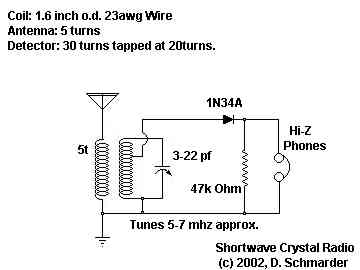
The resonant circuit passes a specific wavelength (or more specifically range of wavelengths depending on its Q). The diode detector provides the amplitude or envelope of the signal(s) within that wavelength. A high impedance or highly sensitive ear piece converts this envelope to an audible signal that you can listen to.
The neat thing about crystal radios is that no active RF amplification is used. The radio is powered by the incoming radio signal that it is tuned to. More sophisticated crystal sets might have more than one tuned stage, perhaps 3 or 4 to minimize receiver bandwidth for maximum sensitivity and selectivity.
History lesson:
[Source: antiquewireless.org
The best analysis written on Titanic’s radio systems can be found in paper format only, Eric P. Wenaas, “Wireleess Equipment of the Titanic: a Commemorative Overview.” Antique Wireless Association Review, Volume 25, 2012.
Advanced concepts in crystal radio design:
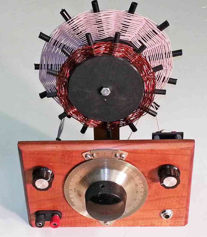
Like the Titanic and other early wireless receivers, Jim wound his own coils, used wood enclosures and point-to-point wiring. With copious use of Litz wire to maximize the Q, Jim has created numerous variants on the crystal radio all of which are shown on his page.


Jim has even created names for some of these radios, such as the ‘hobbydyne’ receiver which is available as a kit.


There’s more:
Jim is not the only one, there exists a community of crystal radio designers and videos of much of their work is shown with a quick search.
You can even add a BFO to copy CW and SSB (which arguably turns your crystal set into a direct conversion receiver where the detector diode becomes your frequency mixer):
To the garage!
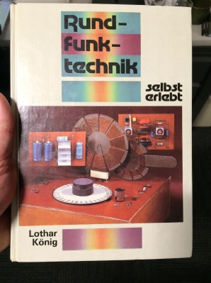 Learning by building a crystal set is ubiquitous. A how-to book from East Germany on radio with a crystal set prominently featured.
Get back to basics and make a crystal radio. Learn about resonant circuits, experience history, wind high Q inductors, make antennas, and experience the fundamentals of wireless design.
Author Bio:
Gregory L. Charvat, Ph.D, likes to study old technology to inform tech development in the 21st century, is CTO of Humatics Corp., author of Small and Short-Range Radar Systems, co-founder of Hyperfine Research Inc. and Butterfly Network Inc. (both at 4catalyzer), editor of the book series Modern and Practical Approaches to Electrical Engineering, guest commentator on CNN, CBS, Sky News, and others. As visiting research scientist at MIT Media Lab he created the Time of Flight Microwave Camera. As technical staff at MIT Lincoln Laboratory he created a through-wall radar imaging system that won best paper at the 2010 MSS Tri-Services Radar Symposium and is an MIT Office of the Provost 2011 research highlight. Greg has taught short radar courses at MIT, where his Build a Small Radar course was the top-ranked MIT professional education course in 2011 and has become widely adopted by other universities, laboratories, and private organizations.


When the Montreal CBC still broadcast on AM I used a crystal radio as a tuner feeding into my audio system because it provide an incredibly clean signal. Mind you we were living very close to the transmitter at the time, and I suspect most of the improvement was due to the fact that the regular receiver was being overdriven.
I used to live next to an FM radio station. I didn’t need a crystal radio. A piece of wire and the magic of slope detection was all it took!
When I was a kid, we used phone speakers with a germanium diode soldered between the terminals. One terminal wire went in the mouth (ground), the other one connected to the downspout. Made a great “portable” radio.
Come on,a stinkin’ diode? Real crystal radios use a galena and cat’s whisker. That’s the experience!
Or you can roll your own precision crystal detector.
http://solomonsmusic.net/CrystalDetector.html
And “foxhole radios” sometimes used a Gillette Blue razor blade and the graphite “lead” of a pencil.
[citation please]
https://en.wikipedia.org/wiki/Foxhole_radio
When I was a kid, I built a lot of crystal radios. I used blued razor blades, I also found that the black oxide on my carbon steel pocket knife worked, too. I didn’t use a pencil lead, though, I used a bent safety pin.
I’ve made this work exactly once. After about a dozen attempts to replicate it I am still not sure how I got it to work the first time.
The razor blade and pencil lead attached to a safety pin was my first crystal radio. Add approx 120 turns of magnet wire and a high z headset and you were listening to AM radio. Getting the ‘sweet spot’ on the razor blade was a challenge, though.
:)
I could be responding to a troll or a variant of Poe’s law. I reply for the benefit of newcomers who don’t have the experience to recognized baloney when they read it. The 1N34 package contains a cat whisker and a a bit of galena/Germanium, that’s why they are such delicate creatures. Te combination of the rock and cat whisker creates a diode it’s out in the open.. A 12 one way or a dozen the other way.
Unless you buy a “1N34” on ebaY from China – then there’s no telling what’s inside.
Yup, a diode with a small Vf is very fundamental, the earpiece crystal determines the use of this circuit. if the goods are fake then the results are fake.
You should ask the seller of the “1n34a diode” with an uncertain authenticity to make sure the Vf is around 0.2 to 0.3volt.
You should use USSR NOS diodes from the Soviets and high impedance speakers which can convert the slightest voltage into sound, even a voltage of a few microvolts from your fingers can make a “click” sound from a voltage of almost 0 volts.
I was really disappointed that my first attempt failed because of my collaboration with an irresponsible seller who claimed a “zenner” type diode with a random filling whose color was passed off as an antique 1n34a by setting a very high price.
but luckily I met an honest seller, saving my hope in the crystal radio project, I almost gave up hope and thought that the crystal radio was a mere conspiracy, just like a fake videos of free electrical and internet electronic circuit made from used speaker magnets at YouTube ;))
A crystal radio was the very first circuit I built. I was 9 at the time, which makes it, what, 49 years ago. Still remember the first time I actually heard a station come in. I think the satisfaction I felt at that moment is what started me off on being a maker my whole life. Everyone should build one with their kids. It just might start them on a very satisfying path in life.
I would recommend “Voice of the Crystal” by Friedricks as a great book, too.
https://www.amazon.ca/The-Voice-Crystal-Peter-Friedrichs/dp/0967190509?ie=UTF8&*Version*=1&*entries*=0
My first radio build was a “foxhole” radio I found in an old book. I used an old razor and a piece of graphite from a pencil tied to a safety pin. I remember it used 128 turns of wire on a cardboard roll. A crystal earphone connected across the safety pin and razor. I actually heard stations with it.
After I built it, my Dad bought me a crystal radio kit that had a tuning capacitor. I had about 70 feet of old wire strung between two poles for my antenna and used to listed to AM stations all over the world at night.
I had a Rocket Radio and crystal radio kit which provided lots of listening when I was suppose to be asleep. I remember using the earphone from the RR with the pencil lead, safety pin, the old razor blade, and the coil wound on a toilet paper roll. Seems like having an antenna wire running out my bedroom window would become the norm.
Fun stuff. My crystal radio sits under my NAD receiver in the rack… Have not used it in 15 years though.
These guys keep using Litz wire as though it’s actually obtainable (for a reasonable price…). Anybody know where to get the stuff for anywhere near the price of braid or magnet wire?
Yes, actually. I gutted an old Dell trinitron CRT a few weeks back because I wanted the wire from the deflection yoke. To my surprise, it was all litz wire (if google images is showing the correct image – multi-stranded, twisted together, individually enameled).
Though now the issue will be finding old junk CRT monitors. ;)
Yeah, not a very sustainable source…
I purchased some on ebay- search for ‘litz wire’ and you will see a number of entries.
Yeah, at 6-10x the price of magnet wire, pound-for-pound or ohm-for-ohm in small quantities. It’s the biggest cost in the BOM for a device I’m designing, and that pretty much cans the project.
You’d think with non-contact charging and inductive cookers being so popular now that the price will have come down for Litz wire, but it hasn’t. It’s still hovering stratospherically around 50x the cost of the copper.
I believe the traps on my Hustler BTV antenna use litz wire, at least the 80m trap does. And there’s http://www.litz-wire.com/index.php
I’ve been able to purchase Litz wire on ebay. Trick is getting the right Litz optimized for your wavelength of interest.
Try here?
http://www.surplussales.com/Wire-Cable/LitzWire.html
https://www.surplussales.com/wire-cable/LitzWire.html
http://www.mwswire.com/litzwire.html
http://www.amazon.com/s/?ie=UTF8&keywords=litz+wire&tag=googhydr-20&index=aps&hvadid=87733539171&hvpos=1o2&hvexid=&hvnetw=g&hvrand=11518008956601811926&hvpone=&hvptwo=&hvqmt=e&hvdev=c&ref=pd_sl_77g45apaow_e
I found that the $2 dollar shop has cell phone charging cords and if you strip the plastic insulator away your left with 4 independent insulated wires also strip the ends bare you’ll find that there’s plenty of strain wires in them and at the small scale of a.w.g which would resemble litz wire with out the silk cover
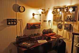
If you’re ever in upstate New York stop by the Antique Wireless Association museum. It’s a great history lesson.
BTW, that 3D rendering is not a rendering it’s a physical period correct installation of the room at the museum!
Do you have any POC’s within AWA? I think it would be great if they could post a .pdf of this article, Eric P. Wenaas, “Wireleess Equipment of the Titanic: a Commemorative Overview.” Antique Wireless Association Review, Volume 25, 2012. Just having this on the web to share would generate a great deal of interest in antique radio.
I’ll send an email and see what I can do.
I’ll second that! Would love to read it!
The author copyrighted the work and does not allow it. They are available for purchase at the museum. Perhaps you could try calling and they could mail it?
I already have a paper copy. This is for the community at large, to reach a wider audience and inspire the masses, post it online.
My parents and I listened to AM news about Hurricane Hazel in 1954 when it hit Toronto. I was 5 :)
There were some schematics of crystal detector in soviet era radio construction book where crystal detector was followed by single bipolar germanium transistor powered by… ground battery (different metal poles dug in to the ground). I had not ground near by (lived on the 6th floor) so I decided to power from single AA battery – yes that was quite good one 0-V-1(?) receiver (that’s how they marked receivers in those times).
Here is K9QD. Fun to see my video (World’s Largest Crystal Radio) linked on this website. I should follow-up with performance measurements someday and append to the original video. There are several retired Motorola engineers in the Schaumburg Amateur Radio Club (www.N9RJV.org) and they can guide the performance test run and augment with proper equipment and math. I’m fortunate to have three 50KW broadcast transmitters within a ~20 mile radius and was able to run ~120 foot long-wire antenna out a tree in the back yard. Plenty of tank resonance voltage to forward-bias a blue/white LED as detector. Also have an antique galena detector-stand that needs to be compared in the test runs. Lots of fun.
Nice work, K9QD. 73 from a fellow ham.
Excellent work!
Marcfoni room indeed there’s a hack.
You can make your own Litz wire using old steam driven ticking clocks, I often haunt charity ships during chuck out night and found 3 good ones for free the other evening.
Often the wire isn’t enameled and another way is to get thin wire from craft shops as this often has a nice coating on it.
Then simply make a jig and wind up the 25 odd strands until it looks about right, and wind away.
contrary to popular belief you *can* join bits of wire made like this by butt splicing the individual strands in batches with very little loss of Q, I have done this to patch up an old microwave transformer as well as a CFL driver from a large LCD TV.
Another source of Litz can be found from the aforementioned old driver boards, Ebay is your friend here.
Typically you will need 10-15 transformers and join the carefully unwound primaries together to make your coil, then use a solid former such as the thick cardboard inner from some sticky label rolls to make your coil.
Also relevant, I hold the copyright for “Method of building a radio using old TV IR receivers” and this uses an infrared LED forward biased to just below its light emission threshold with a resonant tank tuned to 34, 36 or 57 kHz depending on your 3 pin receiver’s center frequency. This isn’t technically cheating as IR receivers were never designed for this, but because it uses a narrow filter it makes a passable FM receiver as well if you add a slope detector.
I had it working on my GM counter to send events and it worked brilliantly, hope to publish in EPE very soon.
These chips only need fractions of a mA and are basically the same as a MK484 inside with the notable exception of an on-chip filter, shield and IR diode instead of a tuned circuit.
“Crystal Radios”, isn’t she an opening act for Taylor Swift?
B^)
Love It!
Cheers and 73’s all:) VK2 Down Under
New South Wales Sydney AUS
Peter
Thanks for the article Gregory. A small correction – Jim’s last name is not Cushman. It’s actually Frederick. I think the confusion stems from the fact that the main site, which contains his crystal radio pages, is called “Jim’s Cushman Scooter & Crystal Radio Site”. I know, because I made the same mistake.
Anyway, I’m a big fan of both Jim Frederick and Dave Schmarder, and their wonderful crystal radio creations. Am hoping to build a set containing Jim’s Hobbydyne circuit soon.
Dave
AA7EE
i had a crystal radio in the late forties and early fifties. I used to catch cloud bounces and hear Yma sumac do amapola from chilie or brazil. Loved them and spent my entire life in technology. i would love to talk to you i have a possibility of creating a market you didnt even think of and if i could get a kit together that i could sell at a reasonable price we might all do some good out of this.