[Joekutz] wanted to re-build an audio-rate function generator project that he found over on Instructables. By itself, the project is very simple: it’s an 8-bit resistor-ladder DAC, a nice enclosure, and the rest is firmware.
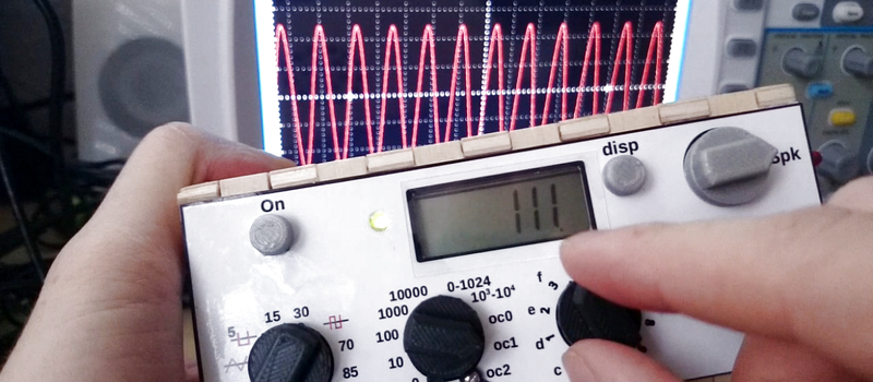
[Joekutz] decided this wasn’t enough. He needed an LCD display, a speaker, and one-hertz precision. The LCD display alone is an insane hack. He reverse-engineers a calculator simply to use the display. But instead of mapping each key on the calculator and typing each number in directly, he only taps the four 1, +, =, and clear keys. He can then enter arbitrary numbers by typing in the right number of ones and adding them up. 345 = 111 + 111 + 111 + 11 + 1. In his video, embedded below, he describes this as a “rather stupid” idea. We think it’s hilarious.
The meat of the project is the Arduino-based waveform generator, though. In the second video below, [joekutz] walks through the firmware in detail. If you’d like a simple introduction to DDS, check it out (or read up our more in-depth version).
He also makes custom detents for his potentiometers so that he can enter precise numerical values. These consist of special knobs and spring-clips that work together to turn a normal pot into a rough 8-way (or whatever) switch. Very cool.
So even if you don’t need an R-2R DAC based waveform generator, go check this project out. There’s good ideas at every turn.


Great Idea to hack the calculator display, bonus points
I love how he used the calculator and it fits in so well with battery operation.
+111
I just want to reiterate that if you’re using ordinary 5% resistors, there’s no point in going up to 8 whole bits of precision: such resistors themselves are only accurate to 4-5 bits.
Even if you get 1% resistors, that’s only 6-7 bits.
I understand your point but there is a difference between precision and linearity. The inaccuracy of the resistor used for the least significant bit is *not* the percentage grade of the resistor (at worst case) it is % * (1 / (2 ^ (bits – 1)).
The situation you are describing is this –
Bit 8 (MSB) 5% resistor
Bit 7 10% resistor
Bit 6 20% resistor
Bit 5 40%
Bit 4 80%
Bit 3 160%
Bit 2 320%
Bit 1 (LSB) 640%
The actual situation is this –
Bit 8 (MSB) 5%
Bit 7 5%
Bit 6 5%
Bit 5 5%
Bit 4 5%
Bit 3 5%
Bit 2 5%
Bit 1 (LSB) 5%
The issue is that when the resistors only have an accuracy of 5%, the MSB on its own can vary by 5%. If we have eight bits and write 0x80 (128, only MSB on), it should represent exactly half the reference voltage (which we’ll take as 1). However, due to the inaccuracies in the resistors, it could be up to 5% higher or lower than half, so 0.5 ± 0.025. The LSB represents 1/256 of the reference = 0.0039 ± 5%, so the error in the MSB is 6.4 LSB. 6.4 is 2^2.678, so the last 2.678 bits should actually be smaller than the possible variation in the MSB. Therefore only the first 5.3 bits are guaranteed to be worthwhile. Assuming the next 7 bits are represented perfectly, 0x7A (122) would actually be just slightly larger than 0x80 when the MSB is 5% low. (Of course, the next 7 bits won’t be perfect. If they’re also out 5%, but in the other direction, it’d be even worse. Or if they’re out in the same direction, everything is linear.)
I should do up some graphs for this. Your perspective is the common perspective but your math is incorrect because the +/- 5% of the LSB actually represents 0.019% and NOT 5% of the reference so while it doesn’t contribute to precision it will still contribute to linearity.
That’s what this is, an Audio output, where Amplitude is most often specified on a logarithmic scale anyway because linearity is more important than precision.
Take for example a measurement of Total Harmonic Distortion (THD). The lower bits will increase the dynamic range available above the THD floor even when not precise because even at 5% a bit is never going to have more influence on the output then a more significant bit.
I agree that on a purely precision scale that 5% resistors are not the best but they are more usable than you might think for real world situations. Our ears have a logarithmic sensitivity so this while not perfect is more useful than you would expect. Much the same applies to out color / contract perception so once again 5% yields usable results.
Of course it would be better if you had some 1% resistors lying around.
Precision measurement equipment would of course need trimmed resistors.
Keep in mind that non-precision measurements like a scope are specified at +/1 3%
I will try to do some graphs.
Any suggestions on what to use for graphs peoples? I normally use JavaScript and older HTML.
“Any suggestions on what to use for graphs peoples? I normally use JavaScript and older HTML.”
You should use a giant animated gif to show us, say around 40 MBs? ;)
I think JS would work IMO.
It’s pretty easy to show that using X% resistors will produce nonmonotonic results after log2(1/X%) bits. Just try modeling a six-bit DAC assuming that all your “2R” stages are 5% high and all your “1R” stages are 5% low; at that point you’ll see unambiguous distortion from the 1000.. step to the 0111.. step.
Will you notice it? I dunno, but it’s definitely there and definitely causes distortion and arguing that it doesn’t is factually incorrect.
But I don’t even consider the error in the LSB, I’m looking at the error in the MSB. My only mention of the error in the LSB was as ± 5% of the LSB, which works out as you say. The error in the MSB still causes a step ~6 times larger than the LSB, instead of the same size.
But as you say, for audio and such like the extra bits are still useful.
I am putting the code together now. It will consist of two sets of drop down lists for parameters.
And various resulting graphs that include results from each parameter group for comparison.
The inputs are –
Tolerance: 5%, 2%, 1%, 0.5%, 0.1%
Optimization: Worst precision, Worst linearity, Typical precision, Typical linearity
Mode: Linear, Logarithmic
Bits: D7 – D0, D7 – D1, D7 – D2, D7 – D3
Graphs will be –
Linear Precision
Linear Linearity
Linear Proportional
Linear Distortion
and the same again as log graphs.
I will probably drop some graphs on HAD.io but the actual simulator will be somewhere else because I can’t embed on HAD.io
I did ask the HAD.io team about this on their feedback form but the result was ‘open loop gain’ which we all know is what happens when you get NO feedback.
I knew that for a (very) precise DAC, 1% resistors should be used – i didn’t, and just used the usual 5% (?) ones. 8 bits still make sense though as RÖB showed below. The precision is actually pretty great as shown with the waveforms on the scope – no spikes or bent curves (in the sawtooth e.g.). Of course, this is clearly not a professional-grade generator.
the four button calculator hack is genius.
How does he represent, say, 101?
With a lot of typing ;) .. 101 = 11+11+11+11+11+11+11+11+11+1+1
or just by keying 1 101 times in all
Works as well, yes :) but my Arduino-function is designed to minimize the number of keypresses as I don’t want to wait forever to get a number displayed.
A bigger question is how does he represent -ve numbers.
A truly useless (but fun) hack, as the time spent reverse-engineering and coding probably exceeds the shipping time of a HD44870 device from t’internet. See https://hackaday.com/2016/08/09/yak-shaving-hacker-mode-vs-maker-mode/
“-ve numbers” ?
Shipping stuff from good old china to europe takes sometimes surprisingly long ;) But I generally agree – there is no real reason to hack a calculator like I did, neither time- nor efford- nor price-wise. In the “Yak-shaving”-article terminology, the whole thing was a pure hacking-project, while e.g. my build here https://hackaday.io/project/6845-desktop-size-cnc-milling-machine-from-scratch was a clear making project.
Hacking the calculator to use its display was actually a brilliant, cheaper-than-HD44870, gotta-have-it-now idea. Things went wrong when you decided on only using four keys. And then the added parts to actually drive the thing made it more expensive than said HD44870.
But at least it was fun to watch. :D
I think using only four keys was excellent… it is the absolute minimum required to implement the functionality he required, and certainly not a “wrong” choice I say! Yes, he could have used more – he could have done them all I suppose. But that would classify it as a waste of time (brute force problem solving) rather than a clever hack (using your brain).
The audio part (to me) is nothing special, but using a calculator as a display device really is a clever/obtuse hack. I take my hat off to you sir for getting the job done with what you had on hand rather than buying your way out of a problem like so many seem to do these days.
Well.. using more than four keys would have required more than four transistors / arduino-ports / efford / nerves .. given that a HD44870 can be bought for $3 or so the whole idea does not make sense in the first place. But at least it was fun to build :D
e will have to call this numbering system “oneary”