Resistor: A passive chunk of material that resists the flow of electrical current. A terminal is connected to each end you’re done. What could be simpler?
It turns out it’s not so simple at all. Temperature, capacitance, inductance and other factors all play a part in making the resistor a rather complex component after all. Even its uses in circuits are many, but here we’ll just focus on the different types of fixed-value resistors, how they’re made, and what makes them desirable for different applications.
Let’s start with a simple one, and one of the oldest.
Carbon Composition
These are often referred to as “old” resistors and were widely used in the 1960s but with the introduction of other types of resistors, and their relatively high cost, they’re used less now. They consist of a mix of ceramic powder and carbon bonded together using resin. Carbon is a good electrical conductor and the higher the concentration of carbon in the mix, the lower the resistance. Wires are attached to the ends. They’re then coated with paint or plastic as an insulator and different colored stripes are painted on to indicate the resistance value and tolerance.
The resistance of these carbon composition resistors can be permanently changed by long exposure to high humidity, being overstressed by voltage and by overheating when soldering. Tolerances are 5% or greater. Given that they’re basically just a solid cylinder they have good high-frequency characteristics. They also have a good ability to resist heat overloading comparable to their small size and so they’re still used in power supplies and welding controls.
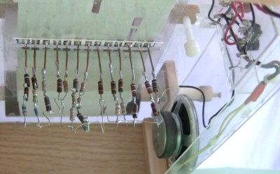
However, their age didn’t stop me from using a bag of them I’d bought from a second-hand store in order to make up the different resistances I needed for a 555 timer music player. That’s my kludge you see in the photo above.
Carbon Film
The Temperature Coefficient of Resistance (TCR) of carbon film resistors is typically around 200 and 500 ppm/C. 200 ppm/C means that for every 1C the resistance will not change by more than 200 ohms for every 1 Mohm of the resistor’s value. In terms of a percentage it’s a change of 0.02%/C. So for an 80C change in temperature, 200 ppm/C means a 1.6% change in resistance or 16 kilohms.
Carbon film resistors typically range from 1 ohm to 10 kilohms, have power ratings from 1/16W to 5W and can handle voltages in the kilovolts. Typical uses are for high voltage power supplies, x-rays, lasers and radar.
Metal Film
Metal film is made similarly to carbon film, by depositing a metal layer (often nickel chromium) on ceramic and then carving a helix from the metal. According to one document by manufacturer Vishay, after the terminals are attached, the helix was formerly trimmed by grinding or sandblasting but these days the trimming is done using lasers. The result is then coated in lacquer and labelled using color coding or actual text.
Metal film’s resistance change due to temperature are less than carbon film’s. The TCR of metal film is between 50 and 100 ppm/C, which for the 50 ppm/C amounts to 0.005%/C. Using the same example as for 1 Mohm carbon film above, for an 80C change in temperature, 50 ppm/C amounts to a 0.4% change or 4 kilohms.
Metal film also starts at a lower tolerance, 0.1%. They also have good noise characteristics, low non-linearity and good long-term stability plus a wide range of uses.
Metal Oxide Film
This is much the same a metal film resistors except that the metal is often tin oxide contaminated with antimony oxide for resistance. This gives it a better performance than either carbon film or metal film in terms of voltage rating, overloads, surges and high temperatures. While carbon film resistors are rated for roughly 200C and metal film, 250-300C, metal oxide works with 450C. However, they have inferior stability properties.
Wire Wound
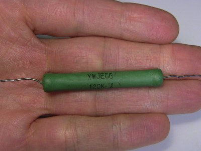
Wire wound resistors are made by winding a wire around a plastic, ceramic or fiberglass cylinder. Since the wire can be cut to a precise length, these can have a high precision resistance value with a tolerance of 0.1% or better. To get a high resistance the wire has to be very thin and very long. The wire can be thin for lower power ratings or thicker for higher power ratings. It can be made of a number of alloys including nickel-chromium, copper, silver, iron-chromium and tungsten.
They’re typically designed to withstand high temperatures depending on the wire material used, pure tungsten ones having a maximum temperature rating of 1700C, though silver ones can be in the 0-150C range. The TCR for precision wire wound resistors is around 5 ppm/C. For high power wire wound resistors the TCR is higher and this varies more.
High power wire wound resistors can range from 0.5W to 1000W and those in the hundreds of watts can be coated in a high temperature silicone or vitreous enamel. For highest heat dissipation there can even be an aluminum case that has fins to act as a heat sink though these seem to be in the 50W range.
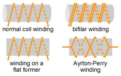
Since the wound wire is basically a coil, they have sufficient inductance and capacitance to have poor properties at high frequencies. To reduce or eliminate this, other ways of winding it are done such as bifilar winding, winding on a flat former and Ayrton-Perry winding as shown in the illustration.
In the case of bifilar winding, induction is eliminated but capacitance is high. By winding on a very thin flat former the wires are close together and induction is lessened. And with Ayrton-Perry winding, since the windings with current in opposite directions are close to each other, self-induction is lessened and capacity is minimized as the potentials are the same at the intersections.
Potentiometers are often wire wound resistors due to the durability. Wire wound resistors are also often used in circuit breakers or fuses. And their induction can be enhanced and put to good use as current sensors by measuring the inductive reactance to determine the current flowing through it.
Foil
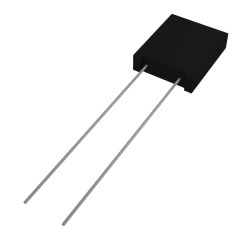
As you might guess, foil resistors use a foil, one that is several microns thick, usually a nickel chromium alloy with additives mounted on a ceramic carrier. They have the best stability and precision of all resistors despite having been around since the 1960s. The desired resistance value is obtained by photoetching a pattern in the foil. They have no inductance, low capacitance, good stability, and rapid thermal stabilization. Tolerance can be as low as 0.001%.
The TCR is around 1 ppm/C. Comparing with the 1 Mohm metal film above, for a temperature change of 80C, that’s a change of just 0.008% or 80 ohms. It’s interesting how this is achieved. As the temperature increases, the resistance of course increases. But the resistor is made in such a way that that increasing temperature causes compression in the foil resulting in a drop in resistance. The net effect is very little change in resistance.
With no inductance, foil resistors are good for audio applications where high frequencies are involved. They also lend themselves to applications requiring precision such as in electronic scales. And of course any location with large temperature swings can also use them.
Thin And Thick Film
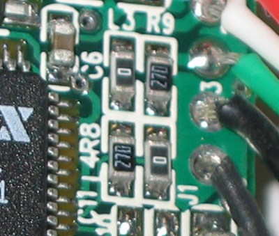
Most Surface Mount Device (SMD) resistors are of this type. The film in thick film resistors are around 1000 times thicker than in thin film resistors and thick film resistors are the least costly resistors on the market. Thin film costs much more than thick film.
Thin film resistors are made by sputtering nickel chromium (usually) onto an insulating substrate. This is then etched using photo etching, abrasive or laser trimming. Thick film resistors are made using a screen and stencil printing process. The film is a mix of a binder, a carrier and a metal oxide. Final trimming is done by an abrasive or laser trimming.
Thin film tolerances are as good as 0.1% and TCR is 5 to 50 ppm/C. For thick film tolerances are as good as 1% with TCRs of 50 to 200 ppm/C. Thin film also has lower resistor noise than thick film.
Typical applications for thin film are wherever high precision is required. Thick film has application in pretty much any electrical device — some PCs contain over 1000 thick film SMD resistors.
Resist No More
There are also other types of fixed value resistors but the above are the ones most likely to be found in people’s resistor drawers. Are there any types that you find specially useful for some application? If so, please share with us in the comments below, along with any other types you frequently use. And if you want another run down on typical components you might find or want for your collection, consider checking out our article on capacitors.


Just remember not to install them backwards….
All the electrons fall out
You just have to kink the wire to stop the flow.
Depends on the frequency, don’t joke too much (:
Unless the bend is “U” shaped, in which case the electrons will be pulled out by siphon action.
I feared, they would fly off the road, especially if they are too fast.
They do fly out if they are to fast.
And doing so emit radiation and create ozone.
Stop it, you’re just part of the oil conspiracy! Install enough resistors backwards and you have a free energy device.
Steven, good article but you left out nichrome wire, tungsten filaments, MOVs, PTC resistors, thermistors, photoresistors, strain gauges and the flex sensors from the PowerGlove.
I suppose hookup wire was also omitted ;). But seriously, I think the purpose of this article was to outline components whose primary function is to provide a static resistance. Components that are resistive as a side effect of heating (nichrome, tungsten filaments) deserve an article unto themselves, and components that map some input value to resistance (photoresistors, flex sensors, temperature sensors) are so varied as to defy classification in a single article.
… what dahud said. But thanks for the suggestions. There may be future articles so your suggestions are welcome. I already had varistors, thermistors, photorestistors and flex sensors as candidates but not the others.
Don’t forget to talk about wheatstone bridges when you talk about Load cells/
And Varley (Murry Loop) bridge, Wien Bridge. You could probably do an article for just bridges.
Yes yes! Let’s get that article together. I enjoyed reading this article about resistor types.
As long as I get the wattage rating right the only time I’ve ever been super particular about my resistors is when it’s something like audio where deviation from rating really matters. If you ever want to get into a discussion where this matters… talk to someone building a powered amp, or a guitar foot pedal. They either spend TONS on really good resistors, or spend forever testing a batch of them to find just the right ones. For any project that’s quick and dirty (ie anything with an arduino.. I’ve found the needs are extremely forgiving).
Resistance is Futile
… said the arc welder.
if less than 0.1 ohm….
Thz
You will be simulated!
Being a lazy digital hobbyist, my knowledge of resistors are mainly 4k7 = pullup and 330 = LED no go poof :)
Wire wound resistors are overlooked by many as being old tech, unlike the whizz bang laser, I mean frikin’ laser it must be cool. They tend to have the lowest Johnson–Nyquist noise of any resistor and long term stability can be unbeatable. So if you are trying to make something that requires precision and stability such as a voltage reference don’t overlook wire wound.
oh good, someone brought up johnson-nyquist noise already.
“1.6 ohm change” should probably be “1.6% change” or 16k Ohm change in the case of the 1M Ohm example resistor.
Similar issue for your other examples of tolerance.
Thanks. Looks like I stopped short one step in the calcs on the first one and then that carried through for the rest. Fixed.
This is a great article! Thanks Steven!
It is important to understand that the resistors in a schematic are very different from the physical things we call resistors. You need to know which imperfections you can ignore for the case you are using it.
Here is my personal hierarchy of design considerations for selecting resistors in circuits (apart from form factor):
1. nominal resistance and tolerance,
2. power rating, and
3. temperature coefficient (TC).
4. If there are other considerations beyond 1.-3. then choosing the resistor is a design project on its own.
The most extreme example from category 4. I came across is a project done by former colleagues of mine. The resistor was a voltage divider, so the schematic showed just two resistors. However, the purpose of the divider was to sense the voltage at the output stage of an ultra-stable high-precision 15 kV DC power supply for an electron energy analyzer. This called for 1. high resistance (lest the dissipation fries everything) 2. relatively high power rating (even with high resistance dissipation is significant) and 3. very low TC. And as for 4.: voltage rating had to be substantially beyond 15 kV.
It turned out Caddock, Vishay and others could supply resistors with very high voltage ratings OR with low TC, but not at the same time, at least not in this extreme form. (They do offer extremely impressive components, though.) After considering quite a number of alternatives, the designers settled for a series of 60 resistors of a low-TC type with a reasonably high voltage rating (hundreds of volts). The cost was 30 EUR per resistor. To achieve the overall voltage rating a zig-zag layout had to be used, so adjacent pins (after one zig-zag) are at most 500 V apart. It took the technician two days for the soldering. He took his time to make sure each solder joint would be perfect, and quickly soldered. The whole thing had to be potted for safety. It got nicknamed “shoebox”. Potting was risky, possibly reducing the performance of the resistors through heating and mechanical stress. But it turned out fine, as week-long measurements confirmed.
If i were doing such a resistor, I’d go with more resistors of lower voltage rating. To connect them in series I’d either spot-weld leads directly, or use wire-wrapping around a pin. Spot-welding is the best method as it won’t cause any Seebeck effect. Then I’d put it in mineral oil. It would improve thermal dissipation and make the resistor easy to fix or modify…
I actually had to deal with Seebeck effect across SMT resistors when designing a sensor board with precision op-amp with high input impedance connected to sensor tat generated lots of heat and few millivolts on its output…
Reminds me of the time I had to measure a ~30kV supply – although not to any great precision. From memory we used a voltage divider of around 2000:1, using 2 large 500Mohm (?) wire-wound resistors for the high side. The op-amp was in a metal tin (an oddity to me, used to DIP packages at the time) with a very low leakage current.
To get the reading back, we used PWM over many metres of optical fibre, sufficiently isolating the expensive control system from any possible faults :)
And that reminds me that I once made an HV probe using 25 200Mohm Caddock MX440 resistors (don’t know what type). I didn’t even think to go with higher resistance resistors at the time — would have saved me a lot of connections. Lots of carefully soldered solder bulb connections. I wrapped a mold around each connection and poured wax. The highest I measured was 75kV.
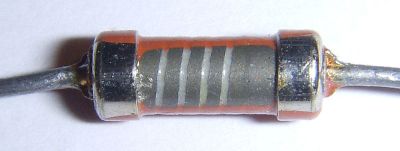
That’s not a spiral on the carbon film resistor, it’s a helix.
And now it’s a helix. Thanks.
I’m currently restoring an old (1946) VTVM, and I found it interesting that all of the resistors were specified to be “metalized” with one exception, a carbon resistor in the RF probe. This caused me, an untrained hobbyist, to take some time to learn about the reasons for the difference before placing an order to replace them all (most were out of spec. 70 years is a long time to maintain calibration).
This excellent article confirms what I learned, so I’m glad to know that I am on the right track.
Thanks, Steven!
I’d like to add something to show i’m smart but I can’t think of nuthin.
That’s okay! You’re doing better than some of the commentators.
That Ayrton-Perry method of winding wire-wound resistors is ingenious. I was only aware of the bifilar winding. Want to reduce capacitance? Make sure the metals which come closeby are at the same potential.
I’d like to know more about power resistors, and especially what could cause one to suddenly not work in… say… a 3D printer Budaschnozzle hot end. Not that I have experienced that. Last week.
And for the sake of completeness:
1) It finished a print just fine.
2) I shut the printer off. Nothing unusual happened.
3) Next print a few days later the hot end would not heat up. I saw no magic smoke on powering it up. Nothing is shorted. Just no heating.
I checked the voltage at the board: fine. Checked the voltage at each solder joint: fine. Checked right up to the leads of the resistor: fine. So it must be the power resistor, right? For those interested, this was a Budaschnozzle 1.2. I’m upgrading to an E3D V6.
I did all of that. Disconnected the cable to check the resistance and got a very telling high-impedance reading.
Had ours go boom about 2 months ago, in the Taz 5. There was an obvious hole burned in the side of it. Not sure why, unfortunately.
Yeah… it’s strange. It was going strong for many years, and finally just gave out. Seems like that should only happen because of an overload or overheat situation of some kind, but an overload would probably have cooked the control board and the resistor seems to be specced correctly for the temperature environment. Maybe they just aren’t designed to last that long, but 4~5 years seems like too short a time.
I haven’t disassembled it yet to look for physical damage. That’ll happen next week probably.
These heating resistors are – of course – very close to an overload condition. The permanently high operating temperature increases aging and weakens the internal structure. But in this case I think the thermal cycles also stress the part. So while hot, it just worked (question how long). But then it broke through thermal contraction or expansion.
I think you’re spot-on. I pulled the extruder from the printer and attempted to measure the resistance of the part. And got an open circuit. Have not been able to push the thing out of its tunnel yet to assess physical damage. I may or may not get around to doing that. First priority is to get the E3D installed, order new filament (switching from 3mm to 1.75mm), install the new extruder (switching from geared to direct drive), update the firmware, and get the printer back in working order. Then *maybe* I’ll worry about what to do with the old parts.
This all reminds me of the time I used a couple of 50W heatsinked resistors to make a reflow plate. It worked well enough, but took many minutes to warm up using my 32V power supply. So one day I got tired of waiting the 10 odd minutes it took to get up to temperature, and decided to just use two powersupplies in series, i.e. 64V. Not a minute later it exploded out the sides of the heatsink – all over my desk. Lesson learnt ;)
Dear Hackaday, this information might be redundant for many of the readers. However it is great info for newbies. This isn’t the first item that falls into this category. I would like to compliment Hackaday with this source of additional easy to read and stimulating educational information, which is spread evenly across the many project related items / posts.
I would like to suggest the following idea: file these (resistors, what uC to choose, etc) topics under a button on top of the page (or other location that can easily be found). For example a button named basic tech info, which clicked on, shows you a list of topic items containing tech info and nothing more, no project, just info. Sorted on publish date or component name in alphabetical order or whatever might be practical. This way the hackaday page can further grow into a quick reference or starting point to more information. This way all hackaday visitors can easily access the information that may lead them to new project ideas and newbies find a place of inspiration (the hack projects) and knowledge (the info topics), so they learn, get inspired and make new hacks that will amaze us or make us smile.
or just use google.
And knowing all this about resistors is kind of moot for this site. If you are in circuit design, you either already know or know all about specs and how to gleen that info from datasheets, contact manufacturers etc….
So its like a reprint of the Wikipedia page for resistors. Still doesn’t tell you shit about building a circuit or even a simple voltage divider for that matter. So you’d have all these random pages written by people that know enough to be dangerous and are often wrong, still doesn’t teach you much of anything useful. There are books and webpages for that.
Hack -a- Day suggests hacks, maybe one a day even. But this “You can electronics” crap needs to be somewhere else, but don’t waste space on the HaD servers for it either…
This is “shit, there are no hardware hack articles to steal from dangerous prototypes today! Quick, write up a recap of Wikipedia and post that!, People hate dead air / no updates….” type of article.
And yet here you come, complaining about something you don’t like. Thanks for the view, which we use as a metric to determine what we should publish more of. Thanks for the comment, too, because that’s an even more important metric of what we should write. Thanks for reloading the page after posting that comment, that’s two views right there. Thanks for mashing F5 in the hopes of seeing a reply to your comment. We love those views and clicks. Thanks for incentivizing what you hate, it really helps out the editorial decisions we make.
Squeaky wheel gets the grease.
If clicks are your only metric you’re doing it wrong.
Re: Educational articles. Yeah!
We just started (in the last year or two) really doing these type articles in earnest. We’re still working on how to best present/collect them all. Because we’ve actually got so many, we’ll have to categorize them a little bit: you don’t want to see articles on microcontroller programming while looking for basic electronics.
In short, great point, and we’re working on it.
Hello,
I’d like to suggest something too : an omnibus like book.
There are great articles about fundamentals in things, and those would make great books.
I already own both omnibooks, but i’d gladly buy such books, even if i already read all the articles :)
One problem with this site is that once it’s burried in the news feed, it’s difficult to find a specific article. For most of the articles, that’s fine, since those are news like stuff, but other articles are reference ones that we (well at least I, since some grumpy hackaday readers will chime in to say that they don’t need those, they see the matrix code, and they program the matrix with a 555 anyway) come back to more often.
Indeed, the site is meant to present news, hacks, etc, but the quality content has made it a good source to learn stuff. And a “fundamentals” section would be neat, a book even better :)
Less commenting, more “Embed with Elliot”ing, please!
Thank you for this article. It outlined the differences very nicely.
I would be glad if you could cover some of the more exotic type as well (Tantal resistors, etc.)
GvTT
Lotta non-hack articles lately.
There are special purpose resistors, current sense, thevenin 4 wire parts with high surge ratings.
Maximum working voltage has to be considered when dividing down very high voltages or dealing with series ESD suppression.
There are fuseable resistors.
No discussion of the near useless-except-for-resistors Millman’s theorem?
No discussion of RULE #1 for Ceramic Resistors:
“THOU SHALT ALWAYS USE A RESISTOR WHOSE POWER RATING IS NOT ONCE, NOT THRICE, BUT TWICE THE MAXIMUM DISSIPATED IN THINE CIRCUIT UNLESS THINE RESISTOR’S MAXIMUM TEMPERATURE RISETH LESS THAN 25 DEGRESS CELSIUS ABOVE AMBIENT TEMPERATUREETH.”
AND SO-ETH IT IS WRITTEN IN THINE TOME OF UL NORMAL TEMPERATURE TESTING.
WIRETH-WOUND-RESISTORS ARE-ETH ALREADY HOLY AND NEED NOT APPLYETH THINE RULE #1.
There are resistors used to generate heat to gently move air across sensors.
Prolly worth mentioning Page 89:
http://snebulos.mit.edu/projects/reference/MIL-STD/MIL-HDBK-217F-Notice2.pdf
Resistance is futile
http://hackaday.com/2016/09/06/what-is-there-to-know-about-resistors/#comment-3184012
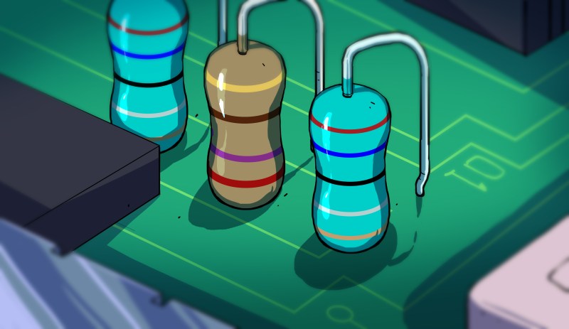
Those green ones in the cover graphic probably are inductors, not resistors. I’ve come across a lot of things that look like through-hole 1/4W or 1/2W resistors in an off-green colour, complete with colour bands, but they were never resistors, always inductors.
Some of them have different colors based of whether they can handle heat.
I’m not saying you are wrong; I would like clarification as well.
I’m pretty sure the one’s you’re seeing as green are intended to be blue (they’re blue to my eyes/brain) like the blue ones in the photo in the section in the article about Metal Oxide Film resistors . Blue and light blue ones tend to be metal film and tan ones tend to be carbon film. That could also result in a correlation with temperature rating at notarealemail points out though my sources are mixed on that. Metal oxide film has a higher rating than carbon film and metal film. My understanding is that there’s no standard though — I could be wrong. From the color code stripes they’re 2.6 ohm 5% resistors. Put red-blue-black-silver-gold in digikey’s calculator here http://www.digikey.ca/en/resources/conversion-calculators/conversion-calculator-resistor-color-code-5-band.
one of the precision series from Vishay actually came in off-green. Not easy to mistake for an inductor though as the specs were never color coded, always printed in open text.
Why do 0 Ohm 0% resistors always read open circuit.
because with a 0% resistor your meter will be 0% accurate ;P
My sandwich made a good resistor! But the pickle factor shorted out the circuit. Burned the mayo and the cheese….it was horror! Horror!
I don’t usually make mistakes, but I may have gone to liberal with the dark matter starter and the turkey bacon combination…next time its plutonium baby! And a rack of ribs!
The page is mostly correct however the treatment of the parasitics of the resistor types is poor. Any circuit element with electrical length with have associated inductance (if the frequency you are considering it allows you to approximate it as electrically small). A leaded film resistor will have an inductance in the 10’s to 100’s nH (depending on size). Even 0402 surface mount resistors become increasingly dominated by reactive impedance at higher frequencies (100 MHz +) limiting the usage of large value resistors. Please see:
http://www.vishay.com/docs/60107/freqresp.pdf
Also, there are some less usual resistors, e.g. the Möbius resistor.
It has no inductance, and it is non reactive at high frequencies.
https://en.wikipedia.org/wiki/M%C3%B6bius_resistor