Got a bunch of questionable electrolytic caps sitting in your junk bin? Looking to recap a vintage radio chassis? Then you might need to measure the equivalent series resistance of the capacitors, in which case this simple five-transistor ESR meter might come in handy.
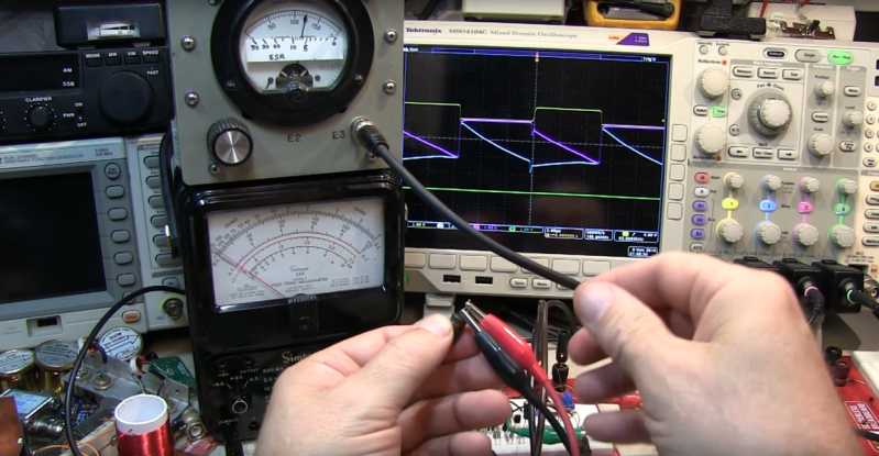
Even if you have no need for an ESR meter, [W2AEW]’s video below is a solid introduction to how ESR is determined. The circuit itself comes from EEVBlog forum user [Jay-Diddy_B] and is about as simple as such a circuit can get. Two transistors form an oscillator that generates a square wave that drives a resistor bridge network. The two legs of the bridge feed matched common-emitter amps, one leg through the device under test. The difference in voltage between the two legs is read on a meter, and you have a quick and simple way to sort through the caps in your junk bin. [Jay-Diddy_B]’s circuit is only presented in breadboard form; no attempt was made to field a practical instrument. Indeed, [W2AEW] already built a home-brew ESR meter using hex inverters and op amps to which he compares the five-transistor circuit’s results. His intention here seems to be to clarify the technique of ESR measurement and evaluate an even simpler circuit than his. We think he’s done a good job on both counts.
We’ve featured plenty of [WA2AEW]’s work before, like this Michigan Mity-Mite transmitter or his primer on oscilloscopes. We really like his laid back style and the way he makes complex topics easy to understand. Check them out.


Quote: “Got a bunch of questionable electrolytic caps sitting in your junk bin?”
The real beauty of an ESR meter is that you can test capacitors *in circuit* which is so much faster than removing them. They make light work of fixing switching power supplies.
I built one based on a PIC probably 25 years ago and still use it often.
As a novice I find that nugget extremely informative. Thank you!. I usually have to employ google foo for WTF is an ESR and whats it used for type things when I come across some HaD articles.
So thanks I learned quite a bit with this article and comments.
Just drain the charge off the capacitors first. I used a 12 Volt car bulb to drain secondary side capacitors. On the rare occasion that I need to drain the primary side caps, I would use a low wattage incandescent house light.
If you design in a 1uF film capacitor (NOT ceramic), then you can test capacitor and battery ESR under voltage.
I did the same recently, esr and capacitance meter using a PIC with auto ranging and in circuit capability and probe compensation, running on two AAA size batteries for compactness. It still has some issues I’ll address in v2 but it also works great as an accurate milli ohm meter too, to measure 4 ohm and lower, down to about 10 mOhm. That’s great to measure inductors, heaters like hotends and heated beds, quality of your soldering etc. I’ve sorted my salvaged caps by esr, excellent are capacitors below the recommended values chart, good are the caps at this value or slightly higher, medium when about twice the esr and bad above that.
In circuit measurement is great but you have to take care, the results can be unreliable, especially when inductors are in the device or when multiple caps are in parallel.
Fun fact was that many probe cables proved to be unreliable as the oxydation on the connectors and/or probe ends/clamps made the zeroing difficult and measurement accuracy unreliable. Good probes really make a difference. I also found out that breadbords have a considerable resistance with all those jumper wires during prototyping. Once put on the pcb the performance was much improved.
I’m always of the opinion that somewhere it should say that ESR is Equivalent Series Resistance. And maybe include an image to make it totally clear.
http://www.yuden.co.jp/ap/product/tech/faq/images/Pic007-002.png
Even though I would say that a very large percentage of the the readers here already know what ESR is and where it comes from, I think that it is worthwhile expanding out TLA’s and ETLA’s at least once.
DOH – it is mentioned, “equivalent series resistance” sorry
Nothing wrong with mentioning it twice though for those that missed it.
For measuring ESR with the help of a microcontroller – there is also this popular open project:
http://www.mikrocontroller.net/articles/AVR_Transistortester
It’s what those cheap ESR meters on ebay/AliExpress are based on.
It has a nice detailed discussion of how to measure ESR with an AVR in its manual (among other interesting things, the project is primarily for automatically testing transistors)
Just be aware that this particular device will not measure ESR in circuit.
I recently got that cheap AVR based thingy and I also have a BK Precision 879B. such a nice device for passive components. I like the cheap AVR too for weeding out my bad transistors and FETs