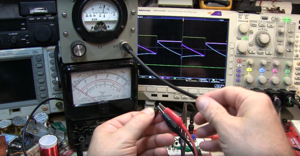
Building A Fake Printer To Grab Screenshots Off The Parallel Port

[Tom Verbeure] recently found himself lamenting the need to take screen grabs from an Advantest R3273 spectrum analyzer with a phone camera, as the older gear requires you to either grab tables of data over an expensive GPIB interface card, or print them to paper. Then he realized, why not make a simple printer port add-on that looks like a printer, but sends the data over USB as a serial stream?

On the hardware side, the custom PCB (KiCAD project) is based on the Raspberry Pi Pico. Obvious form factor issues aside ([Tom] did revise the PCB to make it smaller) this is a shrewd move, as this is not a critical-path gadget so using the Pico as a USB-to-thing solution is a cost-effective way to get something working with minimal risk. One interesting design point was the use of the 74LVC161284 special function bus interface that handles the 5 V tolerance that the RP2040 lacks, whilst making the project compliant with IEEE-1284 — useful for the fussier instruments.

Using the service manual of the Sharp AP-PK11 copier/printer as a reference, [Tom] again, shows how to correctly use the chip, minimizing the design effort and scope for error. The complete project, with preliminary firmware and everything needed to build this thing, can be found on the project GitHub page. [Tom] does add a warning however that this project is still being worked on so adopters might wish to bear that in mind.

If you don’t own such fancy bench instrumentation, but grabbing screenshots from devices that don’t normally support it, is more your thing, then how about a tool to grab Game Boy screenshots?

Debugging Electronics: To Know Why It Didn’t Work, First Find What It Is Actually Doing

Congratulations, you have just finished assembling your electronics project. After checking for obvious problems you apply power and… it didn’t do what you wanted. They almost never work on the first try, and thus we step into the world of electronics debugging with Daniel Samarin as our guide at Hackaday Superconference 2019. The newly published talk video embedded below.

Beginners venturing just beyond blinking LEDs and premade kits would benefit the most from information here, but there are tidbits useful for more experienced veterans as well. The emphasis is on understanding what is actually happening inside the circuit, which explains the title of the talk: Debugging Electronics: You Can’t Handle the Ground Truth! So we can compare observed behavior against designed intent. Without an accurate understanding, any attempted fix is doomed to failure.

To be come really good at this, you need to embrace the tools that are often found on a well stocked electronics bench. Daniel dives into the tricks of the trade that transcend printf and blinking LED to form a plan to approach any debugging task.

Continue reading “Debugging Electronics: To Know Why It Didn’t Work, First Find What It Is Actually Doing”

Getting A Handle On ESR With A Couple Of DIY Meters

Got a bunch of questionable electrolytic caps sitting in your junk bin? Looking to recap a vintage radio chassis? Then you might need to measure the equivalent series resistance of the capacitors, in which case this simple five-transistor ESR meter might come in handy.

Even if you have no need for an ESR meter, [W2AEW]’s video below is a solid introduction to how ESR is determined. The circuit itself comes from EEVBlog forum user [Jay-Diddy_B] and is about as simple as such a circuit can get. Two transistors form an oscillator that generates a square wave that drives a resistor bridge network. The two legs of the bridge feed matched common-emitter amps, one leg through the device under test. The difference in voltage between the two legs is read on a meter, and you have a quick and simple way to sort through the caps in your junk bin. [Jay-Diddy_B]’s circuit is only presented in breadboard form; no attempt was made to field a practical instrument. Indeed, [W2AEW] already built a home-brew ESR meter using hex inverters and op amps to which he compares the five-transistor circuit’s results. His intention here seems to be to clarify the technique of ESR measurement and evaluate an even simpler circuit than his. We think he’s done a good job on both counts.

We’ve featured plenty of [WA2AEW]’s work before, like this Michigan Mity-Mite transmitter or his primer on oscilloscopes. We really like his laid back style and the way he makes complex topics easy to understand. Check them out.

Continue reading “Getting A Handle On ESR With A Couple Of DIY Meters”