Hackers have a long history of overclocking CPUs ranging from desktop computers to Arduinos. [Jacken] wanted a little more oomph for his Pi Zero-Raspberry Pi-based media center, so he naturally wanted to boost the clock frequency. Like most overclocking though, the biggest limit is how much heat you can dump off the chip.
[Jacken] removed the normal heat sink and built a new one out of inexpensive copper shim, thermal compound, and super glue. The result isn’t very pretty, but it does let him run the Zero Pi at 1.5 GHz reliably. The heat sink is very low profile and doesn’t interfere with plugging other things into the board. Naturally, your results may vary on clock frequency and stability.
[Jacken] staggers the shim pieces to afford more exposed surface area. Although copper is a good conductor of heat, using multiple pieces probably mitigates some of the advantage. On the other hand, using thermal compound between the pieces should reduce the microgaps between shims, so that will help.
In addition to overclocking, [Jacken] made some power measurements with all cores active and came up with a surprisingly low current draw (well under 1A). That’s a sample of one, though, so you should probably make your own measurements if it matters
This isn’t the first [Jacken] overclock we’ve seen but the new aspect is the low profile heat sink. If you are just in it for sport, you can overclock an Arduino, even. You can run at 65 MHz, as long as you don’t mind supply liquid nitrogen.


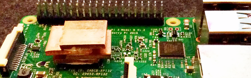
Pi Zero? The photo and article is a Pi 3. 1.2GHz to 1.5GHz with his DIY copper heatsink.
That looks like a Pi 3, not a Pi Zero…
This is not a Pi-Zero
This is a Pi3, you can see the silk screen on the PCB stating Pi 3 Model B v1.2 in the picture below the GPIO pins.
The Pi Zero (like the original Pi A, B, A+ and B+) is also single core, so “with all cores active” suggests a multicore CPU, like the Pi 2B and Pi 3B…
To be honest, the presence of Ethernet, full size USB A and full size HDMI are also a bit of a giveaway that this isn’t a Zero…
I sigh at the lack of attention to detail in this article.
HaaD editors hitting the eggnog already? :D
can you blame them?
With all of us on their comment sections, I hope they can get eggnog by the tanker load!
Strange looking Pi zero in the headder.
also: “raspberry-pi-3-overclocking-heatsink-cheap” << link extract
So three is the new zero?
Also not low profile. Shall take photo of my (personal) Pi2-server with a heatsink salvaged and modified from an old server PCB tomorrow at work (either when I get in around 8ish for resting or at 1st quater break).
As promised:
https://sites.google.com/site/picturedumpunferium/_/rsrc/1482308988448/home/Pi%202%20with%20low%20profile%20hs.JPG
[img]https://sites.google.com/site/picturedumpunferium/_/rsrc/1482308988448/home/Pi%202%20with%20low%20profile%20hs.JPG[/img]
if that did not work, then just copy and paste into address bar:
https://sites.google.com/site/picturedumpunferium/_/rsrc/1482308988448/home/Pi%202%20with%20low%20profile%20hs.JPG
That heatsink is no higher than the pin headers and the whole thing is encased into a steel case containing a HDD and a network dumb-switch for PXE purposes.
Oh I hope HAD staff don’t mind my attempt to insert an inline picture (First time for me to try here)
Well, my bad. I was working on a Pi Zero-related article and this one and just got my wires crossed. The basics are still the same and I’ve corrected it in place. I knew I’d picked the wrong week to stop chugging cough syrup.
Knew it was that time of year. :)
I have an RPi3, and I use these http://www.newegg.com/Product/Product.aspx?Item=N82E16835708012
Coppers thermal interface to free air isn’t that good unless the surface is oxidised. You can do that with a bit of ferric chloride and vastly improve thermal transfer to air.
What really? I assumed oxide ruined most anything
Copper oxide has both high absorptivity, and high emissivity in the IR. The black surface in solar heat systems is usually oxidize copper sheet.
Yes. Black will always radiate the heat better.
That’s why water based radiators in the house is painted white.
To slowly radiate the heat evenly in each room.
Otherwise it would get to warm in the first room.
Many people don’t believe when I tell them this.
Looking at the actual surface area of the copper chunk that is exposed to the air, thermodynamics has one question “huh”?
Exactly my thought. It is a thermal accumulator, not cooler.
And in doing so it provides cooling during transient thermal events and at the same time increases surface area compared to the standard part.
Thermodynamics is okay with this.
Only until that chunk accumulates way too much heat, the CPU just gives up and pops off the board. Not a problem if it’s used for light tasks, but does not seem the case if he needs to OC that Pi.
nothing will pop off, Pee has hidden thermal throttling in the GPU blob firmware.
Well, that is obvious, but the post is about running at higher power, not “turbo” bursts. Putting a larger mass blob of copper on something is a pretty common failure of intuition. If you have to put your finger on the “cold” end, it gets obvious that something is not working as expected.
Yet, I can compile the kernel several times in a row with make -j5 and never exceed 66 Celsius. Where talking about hours of full tilt at 1.5Ghz. So I don’t think I break any thermodynamic rules…
This heat sink is NOT an excellent design but it *is* still better that no heatsink at all.
It’s not really so much of a thermal accumulator as aluminium has a higher thermal mass than copper but copper has higher thermal conductivity and that why heatsinks often have copper tubes from the CPU to aluminium fins at the other end.
Also anodised aluminium or oxidised copper has greater dissipation to air.
The weakest pint of this set up is probably the plastic encapsulation. An electrically insulated heat would probably work better on the other side of the circuit board and the CPU die would have a better thermal connection to the bond wires, pins and then copper traces that the thermal conductivity through the plastic encapsulation.
I will try to get some data from an old post of mine …
With thermals –
Aluminum can *store* heat well but is not good at *dissipating* it so it is good where the thermal load peaks briefly but is generally fluctuating around a low average load like in an office PC. In this situation it will regulate what would otherwise be annoying audible speed transitions of the fan.
Copper can’t *store* much heat at all but it is good for dissipating it so it is good for when you have sustained high loads in performance systems.
Specific Heat Capacity at 25oC in J/g°C (ability to store heat)
Copper : 0.385
Aluminum: 0.900
Emissivity coefficients in ε (ability to transfer heat to air)
Copper: 0.023 – 0.052
Copper with oxide layer: 0.78
Aluminum raw: 0.09
Aluminum anodized: 0.77
Thermal conductivity at 25°C in W/(m K) (ability to move heat away from the CPU and internally)
Copper: 401
Aluminum: 205
Note: The efficiency of transferring heat to air is dependent on the air speed and thermal surface area and therefor dependent on thermal conductivity to transfer heat to that surface area.
The ultimate expression of complete efficiency of heat sink (and optionally fan) is degrees Celcius per watt (°C/W)
He could do much better with something finned.
Much larger surface area to the air.
I’ve even used 1/2 copper pipe flattened out then bent to shape for heat sinks.
Right now Im using aluminum wire mode for heat sinks on led lighting. Works great and is light.
I Luv using aluminum.
AND dont forget the thermo gupe.
while this clearly works I would have tried soldering the copper pieces together as I am sure the solder joints would be able to carry the heat easily enough without re melting. I think solder paste would work better than traditional solder so you didn’t need to just have solder seams to carry the heat to the next copper piece. Does this sound reasonable? Is there a reason this wouldn’t work as well as I think it would in my head?
I don’t see why it wouldn’t work. If the Pi gets so hot it melts the solder, you’ve got a dead Pi at that point, likely from a short circuit across power leads.
That’s what I thought, Thanks I thought I missing something but there is obviously no way you are getting a PI up towards 200c without it breaking.
Indeed, the bottleneck is not the internal thermal resistance of the copper chunks but the much higher thermal resistance from the silicon chip via the plastic case to the copper and even more so the convection heat transfer from the copper surface to air.
I.e. take the specific heat conductivity of ISO standard copper Cu-ETP (CW 004A, ASTM C 11000), which is k = 394W/(m*K) at room temperature. Take a cube of dimension 10mm³. In accordance with Fouriers law of heat conduction, the thermal resistance of uniform transverse heat conduction through a single path (i.e. two opposing surfaces) is then only R_th = x/(A*k) = 0.010m/(0.010²m² * 394W/(m*K)) = 0.25K/W where x is the length and A = x² is the cross-sectional area.
0.25K/W is almost nothing compared to the approx. 50…150K/W resulting from convection cooling. For the derivation of convection cooling, I would turn to the VDI Heat Atlas, but the resulting value depends greatly on the validity of the assumption of unperturbed air flow, which is almost never the case. Anyways, even the chip packaging has a much higher thermal resistance than 0.25K/W.
My advice is then also: Take a finned aluminium heatsink. Silicone-based caulking compund works OK for fixation on top of the package..
i followed your advice, only using superglue for bondage. heck a pi3b runs fine without any methods of cooling. had one running 2 months doing this or that
This video has some great info on passive vs active cooling the Pi 3.
https://www.youtube.com/watch?v=WfQMLInuwws
He went from 1.35 to 1.5?! Ok, keep trying; better results await.
The “lasagne fan” was an ultra-thin heat sink with fan for overclocking systems with limited space, such as the i-opener network appliance (a notebook computer clamped to the back of a LCD). Perhaps they’ll be “rediscovered” for the Raspberry Pi for forced air cooling when using a HAT.
I googled lasagne fan and all I got was hungry.
Had to tweak my search to: “lasagne fan overclocker heatsink” and the first link points to what amounts to a mini version of a PS3 style heatsink but with a fan in the center instead of the side.
Well the lasagna fan kind of looks like lasagne with it’s stacked layers. I wish I could use image software like photoshop. I could have some fun with this.
What was the Normal Heatsink ? something of a MOSFET styled heatsink ?
Per default is has no heatsink… his other heatsink is this one: http://www.jackenhack.com/raspberry-pi-3-overclocking/
Indeed, the write-up is done poorly.
But then, how would I fair doing that job? I mean once you settle into things you tend to start to ‘reduce overhead’.
This calculator ought to not be made use of in circumstances where the warm resource is much smaller sized than the base of the heat sink. The concentration of the warm resource over an area a lot smaller than the warm sink base is not taken into consideration in this calculator.