Make Your Own Pot And Encoder Knobs, Without Reinventing Them

Rotary potentiometers, switches, and encoders all share a basic design: adjustment is done via a shaft onto which a knob is attached, and knobs are sold separately. That doesn’t mean one knob fits all; there are actually a few different standards. But just because knobs are inexpensive and easily obtained doesn’t mean it’s not worth making your own.
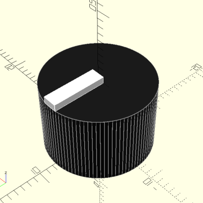
A simple and effective indicator can be easily printed in a contrasting color.

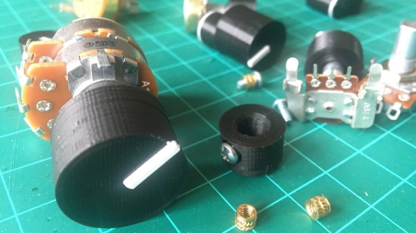
Why bother 3D printing your own knobs instead of buying them? For one thing, making them means one can rest assured that every knob matches aesthetically. The ability to add custom or nonstandard markings are another bonus. Finally, there’s no need to re-invent the wheel, because [Tommy]’s guide to making your own knobs has it all figured out, with the OpenSCAD script to match.

By default, [Tommy]’s script will generate a knob with three shims (for interfacing to a splined shaft) when pot_knob(); is called. The number of shims can be adjusted by modifying potKnobDefaultShimCount. To give the knob a flat side (to interface with D-shafts), change flatted = false to flatted = true. And for adding a screw insert suitable for a set screw? Change tightenerDiameter = 0 from zero to the diameter desired.

The script is quite comprehensive and has sensible defaults, but it does require a bit of knowledge about OpenSCAD itself to use effectively. We have covered the basics of OpenSCAD in the past, and if you’re ready for a resource that will help you truly master it, here’s where to look.

Scanner Snooping Uncovers Focus Farce

From his comments about the noisy image and limited controls, we’re going to go out on a limb and assume [Andrew Jeddeloh] isn’t a huge fan of using his Epson V550 for scanning film. But is it really irredeemable? That’s what he set out to determine in a recent series of posts on his blog, and from what we can tell, it’s not looking good for the old Epson.

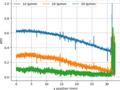
The first post attempts to quantify the optical capabilities of the scanner by determining its modulation transfer function (MTF), point spread function (PSF), and comparing its horizontal and vertical resolution. As you might expect, the nuances of these measurements are a bit beyond the average user. The short version of his analysis is that the scanner’s slide frame does indeed seem to be holding objects at the proper “sweet spot” for this particular image sensor; meaning that contrary to the advice he’d seen online, there’s nothing to be gained by purchasing custom film or slide holders.

MTF versus height of film from bed.

While investigating the optical properties of the scanner, [Andrew] became curious about the automatic focus options offered by the VueScan software he was using. The images produced appeared to be identical regardless of what option he selected, and he began to suspect the feature wasn’t actually doing anything. To confirm his theory, he wrote a shim program that would sit between the proprietary VueScan program and the V550 driver and log all of the data passing between them.

After tweaking various options and comparing the captured data streams, [Andrew] determined that enabling automatic focus in VueScan doesn’t do anything. At least, not with his scanner. He did notice a few extra bytes getting sent to the driver depending on which focus options were selected, but the response from the scanner didn’t change. He thinks the program likely has some kind of generic framework for enabling these kind of features on supported hardware, and it’s just mistakenly showing the autofocus options for a scanner that doesn’t support it.

If there’s some film you want to digitize, but you’re saddled with a scanner like the V550, you could always do it with a camera instead. You could even put together a passable film scanner with LEGO.

Pi Keeps Cool At 1.5 GHz

Hackers have a long history of overclocking CPUs ranging from desktop computers to Arduinos. [Jacken] wanted a little more oomph for his Pi Zero-Raspberry Pi-based media center, so he naturally wanted to boost the clock frequency. Like most overclocking though, the biggest limit is how much heat you can dump off the chip.

[Jacken] removed the normal heat sink and built a new one out of inexpensive copper shim, thermal compound, and super glue. The result isn’t very pretty, but it does let him run the Zero Pi at 1.5 GHz reliably. The heat sink is very low profile and doesn’t interfere with plugging other things into the board. Naturally, your results may vary on clock frequency and stability.

Continue reading “Pi Keeps Cool At 1.5 GHz”

Repair Stuck IPod Nano Buttons

A system is only as strong as its weakest link and [Roberto Barrios] found that on the sixth generation iPod nano the buttons are the problem. It makes sense that the buttons would be exposed to wear since they’re movable parts. The issue isn’t one of contacts or springs wearing out, but how the buttons are assembled. Each consist of a couple of parts; the tactile piece that you see and press, the electrical switch which converts that force into an electrical signal, and a shim that bridges the gap between the two.

After two months of use the iPod [Roberto] was fixing had stopped responding to presses of the Power button. It turns out that the shims are attached with double-sided tape. Inspection of the internals revealed that the shim had slid to one side and no longer made contact with the electrical system. His solution was to remove the tape and clean off the goo, then reattach the shims using “two-part metal cement”.

With the shim back in place all is well but he made sure to execute this fix on all of the buttons before reassembly.