
Phased array antenna systems are at the cusp of ubiquity. We now see Multiple-Input Multiple-Output (MIMO) antenna systems on WiFi routers. Soon phased array weather radar systems will help to predict the weather and keep air travel safe, and phased array base stations will be the backbone of 5G which is the next generation of wireless data communication. But what is a phased array antenna system? How do they work? With the help of 1024 LEDs we’ll show you.
It’s good to first review what phased array antenna technology has been used for in the past, where it is today, and where it is going, then we will show you how it all works.
The Military Industrial Complex: Pioneers in Phased Array Technology
 Phased array technology was pioneered for military applications. The ever increasing speed of aircraft and ordnance after the second world war pushed the requirement for antenna sweep time from seconds to milliseconds.
The first full-scale phased array radar systems was the FPS-85, which is used for detecting and tracking space objects which by their very nature are fast moving.
Additional iconic examples of phased array radar technology include the SPY-1 phased array radar, PAV PAWS, and others.


The First Widespread Use of Phased Array Radar Technology for a Civilian Application:
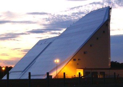
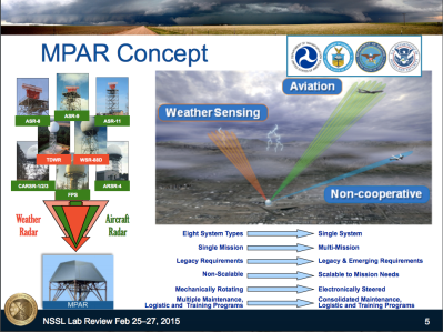
To manage increases in air traffic and to consolidate numerous existing aging radar infrastructure, including most types of primary air traffic control radar and weather radar, the multi-function phased array radar (MPAR) system is under development and prototypes to be fielded soon. This will become one of the first (likely the very first) wide scale civilian deployment of phased array radar technology.
More Wireless Bandwidth for Your Mobile Devices
Key to the 5th generation of wireless systems (5G) is the use of phased array antenna technology, where individual wireless devices will be tracked by beams transmitted/received from the base station thereby enabling greater data bandwidths which are discretized into individual microwave beams.
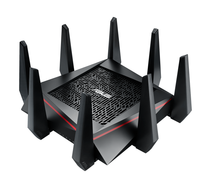
Many WiFi routers now use Multiple Input Multiple Output (MIMO) antenna arrays for the purpose of reducing multi-path signal loss, which is quickly becoming more and more of a problem as data rates increase.
How Do Phased Array Antenna Systems Work?
How do you create a ‘beam of microwave energy’ and direct your receiver onto just the right point in space?
An excellent tutorial is presented here, but the key take away is that if we feed an array of antenna elements with the same microwave signal then we can use these elements to direct (or steer as it is commonly referred to) a microwave beam anywhere in space. This beam steering is achieved by the use of a phase shifter (or its equivalent) in series with each and every antenna element.
To make the above explanation more interesting and understandable, friends of mine at MIT Lincoln Laboratory created this direct visualization of how antenna arrays work (shown recently at the 2016 IEEE International Symposium on Phased Array Systems and Technology). It is almost as if you were to put on a pair ‘microwave goggles’ and looked into the antenna array!
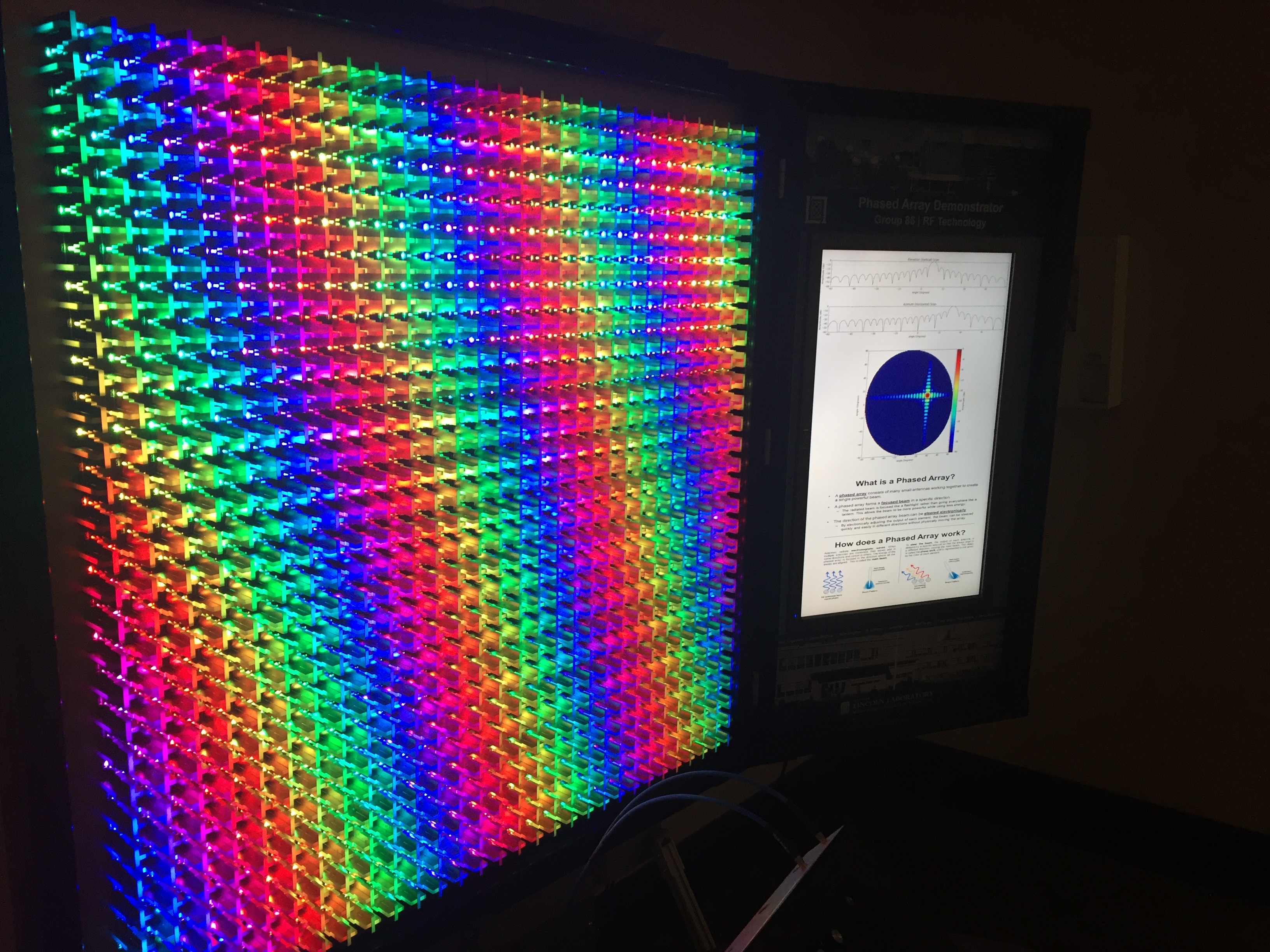
A plexiglass duplicate of an actual phased array antenna system built by MIT/LL is stuffed with NEO Pixel LEDs. Each antenna element is illuminated by two NEO Pixels, where this is a dual-polarized phased array using one LED for vertical and another for horizontal polarization.
The color of each NEO Pixel is mapped to phase of what its respective antenna element should be to project a beam of microwave energy in any given direction and this beam pattern is plotted by the flat-screen monitor next to the array.
The brightness of each LED is proportional to transmit power out of its respective antenna element. The array supports amplitude tapering to synthesize low sidelobe beam patterns and numerous advanced array modes.
With this visualization system, you can manually move the antenna beam around with a joystick and view the lighted pattern and beam plots changing in real-time, providing an instant and intuitive understanding of phased array beam steering and beam patterns. Absolutely amazing!
Summary
Phased array antenna systems will play a central role in our modern lives facilitating greater wireless bandwidths, making airline travel safer, and weather prediction more accurate. Compelling visualizations like the array shown here will facilitate widespread understanding of electromagnetics and modern antenna techniques.


802.11ac does NOT work the same way as the huge military radar arrays do, it can’t really track a device like a planar 2-D array would, it just mangles the output characteristic in some way, that (presumably*) yields the best gain…
*because of the low element count and the unpredictable environment around the antenna array, the beam forming is quite random and thus not not always optimal
if a picture is worth a 1000 words…
http://www.radartutorial.eu/06.antennas/pic/if3.gif
This gif > the post
That image is from the first link under “How Do Phased Array Antenna Systems Work?”
+1
Now I only need a gif explaining on how they use the returned signals. That’s the part of the phase array antenna I still don’t understand.
Basically and vastly oversimplified, the system correlate the signal between each receivers within a time window, trying to find the same signal with just a phase offset between adjacent received signal. The phase offset contain information about the direction of the incoming signal. Multiple signals from different directions can be tracked simultaneously. The process require a lot of computation power, especially to get fast real-time results.
https://en.wikipedia.org/wiki/Reciprocity_(electromagnetism)
The short version: antennas are inherently bidirectional. Just as a generator also works as a motor, a transmitting antenna works as a receiving antenna. Basically, if you phase shift the received signals the same as you do the transmit signal, signals coming from the direction you have the antenna “aimed” will reinforce each other, while signals from other directions will cancel each other out when you add all of the shifted elements together.
Not all antennas are bidirectional, while some phased radio antenna arrays can be bidirectional, most are not. Perhaps reciprocity, as it applies to radio antennas, is the term you are looking for?
Actually, I was trying to AVOID the word reciprocity, since it usually needs further explanation. But now I see that “bidirectional” was an even poorer choice due to ambiguity.
whay?
This gif helped so much! +1
Did the same for me years ago, figured it might do the same for others :D
btw there’s more useful info on the webpage it’s from…
I’d argue that’s NOT different, it’s the same, you’re just looking at it on a different axis.
http://hackaday.com/?s=phased+array
I’ve noticed most hacking involving phased array involves sound which reflects degree of difficulty and the economics. It’s still fun to play with.
That’s what happens when you need not one, but several microwave modules, each containing not exactly cheap parts… some cheapish IC’s for at least C-band T/R modules would be nice to have :D
But the real bummer is that with 2-D arrays, the element count grows exponentially :(
I’d wager the element count grows geometrically.
It scales as the square of the square of the size. However, there is some help here: when systems like PAVE PAWS and the FPS-85 were being developed, of course one of the issues was the expense of thousands of separate elements, both in initial cost and in maintenance. What the designers noticed, though, was that you can leave many of the elements out of the array without having a major effect on the antenna angular resolution. (There is a degradation in gain, but resolution was the main reason the arrays had to be so BIG.) To hide this important discovery, and the research that determined WHICH elements are least important, the military’s phased array antennas appear to have all positions populated, but only about half are active elements.
You only have to do some reading on radio astronomy to fill in the gaps there.
I remember sitting in a meeting suggesting NSSL’s radar to an FAA systems engineer to back ADS-B if it goes down. I worked embedded signal processing for the array(TEP) that sits in Oklahoma. There are some neat synergies that can be had if we do put Aegis Ashore all over the country. I’m sure Europe would love to have them too ;)
Aviation comes down to separation and if we were able to separate planes with less than the 5 mile by 1000 feet spheroid we could squeeze more traffic into the sky. The old radars have a sweep that dictates that volume because you can cover about that distance between blips. Phased array is instantaneous.
https://news.usni.org/2016/05/12/aegis-ashore-site-in-romania-declared-operational
Romania has theirs.
its not used for commercial air flights, though.
its supposed to track a different kind of flying object, but yes, we do have one.
unfortunately the results of the local arliamentary elections brings us back 10 years in collaborative thinking, and forward 10 years in funds embezzling and lining pockets.
no chance of it being used for commercial purposes in the predictable future.
Focused array speakers work in a similar fashion. Take a look at Dakota Audio & Renkus Heinz.
MIMO != Phased Array.
http://www.nutaq.com/blog/mimo-radar-and-phased-array-radar
Thanks for that insight. Good luck with finding a way to demonstrate THAT visually!
Ha you said tree.
OK OK, so they really need to implement a digital holographic display to fully emulate how it functions at visible frequencies, but people still wouldn’t understand it.
Lighten up, Francis.
Yes, a more effective demonstration would be a bunch of solenoids poised above the surface of a water pool, dipping into the water at timed intervals. BUT, this would only show a one-dimensional array (like the gif above).
You’re welcome to propose an effective 2-dimensional array demonstration.
(https://www.youtube.com/watch?v=0OnpkDWbeJs)
AESA (Active Electronically Scanned Array). Modern AESA radars employ miniaturized active radiating elements with integrated frequency/phase/amplitude control, cooling, and adaptive pre-distortion linearized Gallium Nitride (GaN) based power amplifiers. The emerging AESA’s will be conformal, not flat. This will allow the devices to act as adaptive electronic countermeasures in addition to search, targeting, and navigation radars. These things are EXPENSIVE to design and build, especially in a compartmentalized secure environment. But you either pay the money – or lose the war! It’s your choice Mr. & Ms. Taxpayer (of which I am one).
It’s quite interesting that the russians keep using passive arrays even in new stuff and seem to be content with them…(and NATO still seems to be scared shitless of those radars that they call inferior)
If your radar is 20x more expensive, but not 20x as good, it’s not necessarily better, as more radars with poorer perfomance will usually be better then 1.
I believe I don’t have visualizing in my mind the radiation patterns of phased antenna arrays from reading text, but I’m not seeing in in this video. Perhaps if I where at the display and standing back from it. What seems to be beyond me is how the system makes sense of the reflections of the array’s transmissions.
discretized?
I believe this system predates the FPS-85
https://en.wikipedia.org/wiki/GE_AN/FPQ-16_Enhanced_Perimeter_Acquisition_Radar_Attack_Characterization_System
So 3 or 4 phased array antennas on a phone tower should provide better coverage with fewer or no dead or weak spots.
What else could be done with this? More precisely locating mobile phones.
Currently, with a single tower a rough location can be derived from the direction of the antenna(s) used on a tower and the signal strength. That can get direction to the phone, somewhere within the beam angle, and a distance range of much less accuracy.
If the phone call makes a transition from one tower to the next, things like travel speed can be derived. By knowing the precise time of the handover, triangulation of the location can be a lot more precise.
Add a third tower and your location can be nailed down within a few meters or even closer. If you’ve left your GPS and location services on, your rather precise location is being transmitted so with the right warrants the police can get your location without having to use the phone towers to triangulate.
That’s why it’s sooo annoying on TV shows that they’re still doing the have to keep the person on the phone long enough to trace the call shtick. Setup in advance to be hooked into the cellphone system they have the location almost instantly by having multiple towers waiting and ready to report on the time and direction of the phone signal received.
Add beam forming phased array antennas that aim radio beams directly at phones and follow them, tracking a phone that has all location reporting, even e-991, disabled, will be even easier.
nice to see the Cloverfield cameraman getting some work… but yea video shot in gut wrenching coked out cameraman with no image stabilization mode.
If some of the energy from each element of the phased array is going to get cancelled out by the elements next to it (for off-axis beaming) doesn’t it get less efficient the further away from perpendicular the target is?
No. In the big picture all multi element gain antennas all work alike whether colinear gain whips reflector panel or dish or phased array panels. In the deep dive you have an element that radiates a typically toroid pattern. The radiation goes almost everywhere. It is reflected off of other surfaces whether intentionally or not and the reflections have a full range of time delays in all different directions and some line up with the phase of the original signal and some don’t. In areas really close to the radiating element you have chaos. But you get sufficiently far from the element and the reflector and additive signals turn into a plane wave where the power of the reflection adds to the power of the initial radiated wave. This produces directional gain only in the direction where the 2 signals remain in phase. Instead of a reflector, you can use multiple radiating elements to achieve the same results. If you vary the phase of one you can point the direction of the gain. Any graphic that shows directionality occurring at the surface of the antenna is totally bogus as the only directional signal occurs in the far field which is a factor of the frequency and the antenna aperture size. The far field is defined as the area where all waves combine into a single plane wave with less than 1/16 wavelength difference and can occur as far away as a few hundred feel from the surface of the radiating elements.
This is a really wonderful demonstrator and reminds me of the better designed exhibits at science museums. I hope this one ends up at one.