While the average person would use a standard charger to top off their phone, [Tom Stanton] is no average man. Instead, he put mind to matter with an entire pendulum battery system.
Using the inductive effects of magnets on copper coils, [Tom] found the ability to power small components. With that in mind, the only path was forward with a much larger pendulum. A simple diode rectifier and capacitors allow for a smoother voltage output. The scale of the device is still too small to power anything insane, even the phone charging test is difficult. One thing the device can do is juice up the electromagnetic launcher he put together a couple years back to hurl an RC plane into the air.
The useful applications of pendulum power storage might not be found in nationwide infrastructure, but the application on this scale is certainly a fun demonstration. [Tom] has a particular fascination with similar projects where practical application comes second to novelty. For a perfect example of this, check out his work with air powered planes!
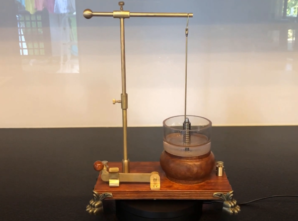
Although new electric motor types are still being invented, the basic principle of an electric motor has changed little in the past century-and-a-half: a stator and a rotor built of magnetic materials plus a bunch of strategically-placed loops of wire. But getting even those basic ingredients right took a lot of experimentation by some of the greatest names in physics. Michael Faraday was one of them, and in the process became the first person to turn electricity into motion. [Markus Bindhammer] has recreated Faraday’s experiment in proper 19th century style.
Back in 1821, the very nature of electricity and its relation to magnetism were active areas of research. Tasked with writing an article about the new science of eletromagnetics, Faraday decided to test out the interaction between a current-carrying wire and a permanent magnet, in a setup very similar to [Markus]’s design. A brass wire is hanging freely from a horizontal rod and makes contact with a conductive liquid, inside of which a magnet is standing vertically. As an electric current is passed through the wire, it begins to rotate around the magnet, as if to stir the liquid.
[Markus]’s video, embedded after the break, shows the entire construction process. Starting from rods and sheet metal, [Markus] uses mostly hand tools to create all basic parts that implement the motor, including a neat knife switch. Where Faraday used mercury as the conductive liquid, [Markus] uses salt water – cheaper and less toxic, although it does eventually eat up the brass wire through electrolysis.
While not particularly useful in itself, Faraday’s motor proved for the first time that electric energy could be converted into motion through magnetism, leading to a whole class of ultra-simple motors called homopolar motors. It would be a while before experiments by the likes of Tesla and Ferraris led to modern AC motors. If you don’t like your motors magnetic, you can use electrostatics instead.
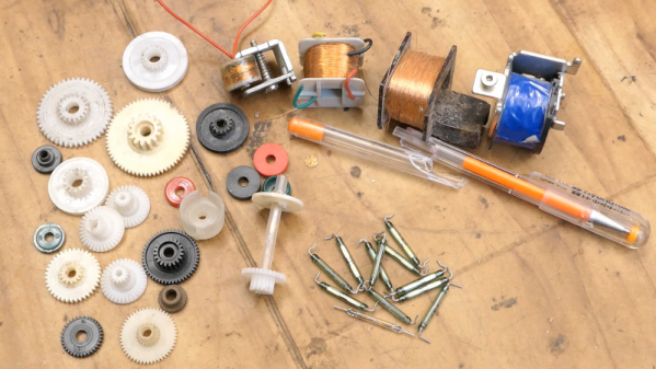
We’ve all been there. Someone will say something like, “I remember when we had to put our programs on a floppy disk…” Then someone will interrupt: “Floppy disk? We would have killed for floppy disks. We used paper tape…” After a few rounds, someone is talking about punching cards with a hand stylus or something. Next time someone is telling you about their relay computer, maybe ask them if they are buying their relays already built. They will almost surely say yes, and then you can refer them to [DiodeGoneWild], who shows how he is making his own relays.
While we don’t seriously suggest you make your own relays, there are a lot of fun techniques to pick up, from the abuse of a power drill to the calculation of the coil parameters. Even if you don’t learn anything, we get the desire to make as much as you can.
[Willem Koopman aka Secretbatcave] was looking at a master clock he has in his collection which was quite a noisy device, but wanted to use the matching solenoid slave clock mechanism he had to hand. Willem is a fan of old-school ‘sector’ clocks, so proceeded to build his ideal time piece — Vibrmatic — exactly the way he wanted. Now, since most time keeping devices utilise a crystal oscillator — which is little more than a lump of vibrating quartz — why not scale it up a bit and use the same principle, except with a metal tuning fork? (some profanity, just to warn you!)
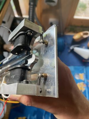
Shock-mounted tuning force oscillator
A crystal oscillator operates in a simple manner; you put some electrical energy in, it resonates at its natural frequency, you sense that resonance, and feed it back into it to keep it sustaining. With a tuning fork oscillator, the vibration forcing and the feedback are both done via induction, coils act as the bridge between the electronic and mechanical worlds.
By mounting the tuning fork onto a shock mounting, the 257 Hz drone was kept from leaking out into the case and disturbing the household. This fork was specified to be 256 Hz, but [Willem] reckons the drag of the electromagnets pushed it off frequency a bit. Which make sense, since its a mechanical system, that has extra forces acting upon it.
The sector face was CNC cut from aluminium, the graphics engraved, then polished up a bit. Finally after a spot of paint, it looks pretty smart. Some nice chunks of upcycled wood taken from some building work spoils formed the exposed enclosure. On the electronics side, after totally ignoring the frequency error, and then tripping over a bunch of problems such as harmonics in the oscillation, and an incorrectly set-up divider, a solution which seemed to work was found, but like always, there are quite a few more details to the story to be found in the build log.
Like any complex topic, electromagnetic theory has its own vocabulary. When speaking about dielectrics we may refer to their permittivity, and discussions on magnetic circuits might find terms like reluctance and inductance bandied about. At a more practical level, a ham radio operator might discuss the impedance of the coaxial cable used to send signals to an antenna that will then be bounced off the ionosphere for long-range communications.
It’s everyday stuff to most of us, but none of this vocabulary would exist if it hadn’t been for Oliver Heaviside, the brilliant but challenging self-taught British electrical engineer and researcher. He coined all these terms and many more in his life-long quest to understand the mysteries of the electromagnetic world, and gave us much of the theoretical basis for telecommunications.
Phased array antenna systems are at the cusp of ubiquity. We now see Multiple-Input Multiple-Output (MIMO) antenna systems on WiFi routers. Soon phased array weather radar systems will help to predict the weather and keep air travel safe, and phased array base stations will be the backbone of 5G which is the next generation of wireless data communication. But what is a phased array antenna system? How do they work? With the help of 1024 LEDs we’ll show you.