Sometimes I see a component that’s bizarre enough that I buy it just to see if I can actually do something with it. That’s the case with today’s example, the ESP-14. At first glance, you’d ask yourself what AI Thinker, the maker of many of the more popular ESP8266 modules, was thinking.
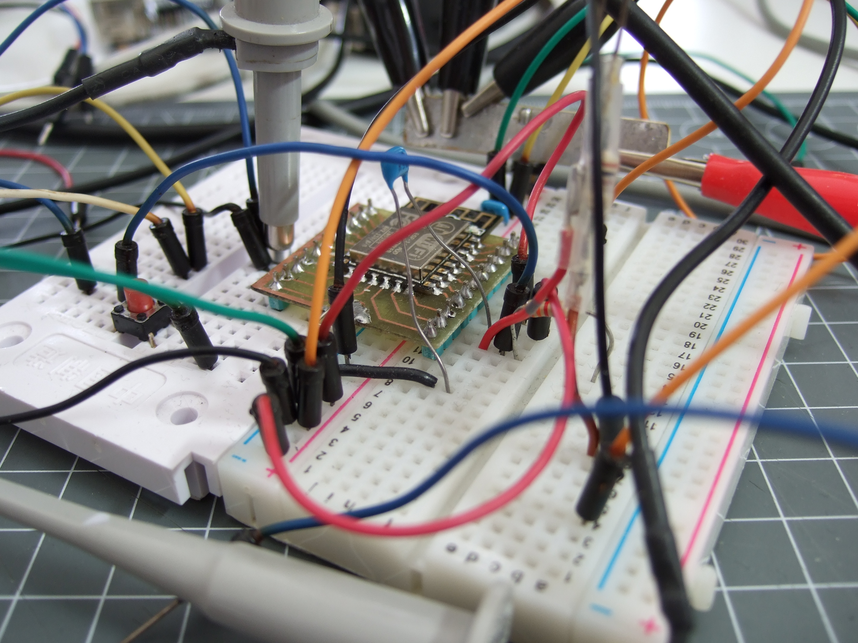
The ESP-14 takes the phenomenally powerful ESP8266 chip and buries it underneath one of the cheapest microcontrollers around: the 8-bit STM8S003 “value line” chip. Almost all of the pins of the ESP chip are locked inside the RF cage’s metal tomb — only the power, bootloader, and serial TX/RX pins see the light of day, and the TX/RX pins are shared with the STM8S. The rest of the module’s pins are dedicated to the STM8S. Slaving the ESP8266 to an STM8S is like taking a Ferrari and wrapping it inside a VW Beetle.
I had never touched an STM8 chip before, and just wanted to see what I could do with this strange beast. In the end, ironically, I ended up doing something that wouldn’t be too far out of place on Alibaba, but with a few very Hackaday twists: a monitor for our washer and dryer that reports power usage over MQTT, programmed in Forth with a transparent WiFi serial bridge into the chip for interactive debugging without schlepping down into the basement. Everything’s open, tweakable, and the Forth implementation for the STM8S was even developed here on Hackaday.io.
It’s a weird project for the weirdest of ESP modules. I thought I’d walk you through it and see if it sparks you to come up with any alternative uses for the ESP8266-and-STM8S odd couple that is the ESP-14.
Putting a Dumb Chip on the Net
The STM8S series of 8-bit parts are, well, cheap. Consequently they show up in all manner of commercial products where a bare minimum of microcontrollering is needed. And consequently, there are a lot of Chinese designers who are familiar with the chip, which is where things start making sense again. According to the ESP-14 datasheet (PDF mirror of a datasheet we downloaded from Watterott), the intended use is to provide WiFi connectivity to the diminutive STM8S, through UART and using the ESP8266’s default AT command set firmware. Which is to say that if you’ve already got a slightly fancy light switch design that uses an STM8, you’re just a few AT commands away from having a super fancy IoT light switch with the ESP-14.
And the ESP8266 modules all have an Achilles heel: the single ADC channel. So if you wanted to make an Internet-connected device that reads more than one analog value, you had to add your own multiplexer circuitry. Or use it in combination with a common, cheap microcontroller with a built-in ADC and some free pins. And thus, we conjecture, the bizarro ESP-14 was born.
Resources and The Plan
The STM8S provides multiple ADCs, and the ESP8266 brings WiFi connectivity and a lot of memory into the mix. I was trying to think up a project for this combination. At about the same time, my wife wanted a monitor that would tell her how the washer and dryer were doing without walking all the way down to the basement. Two ADCs, one for each appliance, would be necessary. Perfect. Can’t do that with an ESP-12!
ST has a fairly complete looking Standard Peripheral Library in C for the STM8 series that should make getting stuff done pretty easy. If you’re looking for other resources, The Way of the Register is full of good working examples for most nooks and crannies of the STM8S’s hardware. Compiling for the STM8S is supported by SDCC, and uploading code using cheap ST-Link dongles is supported by stm8flash. You’ll probably also want the datasheet and the reference manual.
 But this is a strange project, and that means a strange programming language. I’ve been playing around with Forth a lot lately, and [Thomas] ported a Forth environment to the STM8S over on Hackaday.io. If you’re not into Forth, it’s an interactive programming language that’s somewhere between Python and assembly, but with the syntax of an old TI calculator. It’s an acquired taste, but being interactive means that it requires a serial connection to program.
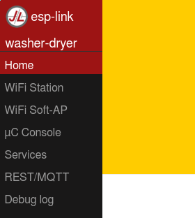
JeeLab’s esp-link is a great tool to have in your box. The software turns any bog-standard ESP module into a transparent WiFi-to-serial bridge, and it adds all manner of bells and whistles. These include providing the connected microcontroller MQTT and REST functionality over a SLIP interface. For this project, it is a perfect fit: the ESP8266 half of the ESP-14 module would let me call in to the Forth interpreter running on the STM8, and provide it with a “simple” means to send out the washer’s and dryer’s power usage to an MQTT broker. This means that I could build up the circuit, install it in the basement, and hack away from the comfort of my office. Almost.
Reset and Power
Programming in Forth, at least when I do it, means hitting the reset button a lot; hard crashes usually take down the interactive shell running on the microcontroller. Fortunately, esp-link provides a reset functionality from the web interface of the ESP8266, and it’s possible to remap this to the single exposed ESP8266 pin (GPIO0) from the esp-link’s web interface. The end result is that the STM8S can be reset by sending a POST request to the ESP: curl -XPOST "http://${ip}/pgm/sync" if you care. After a couple of seconds, all is well again.
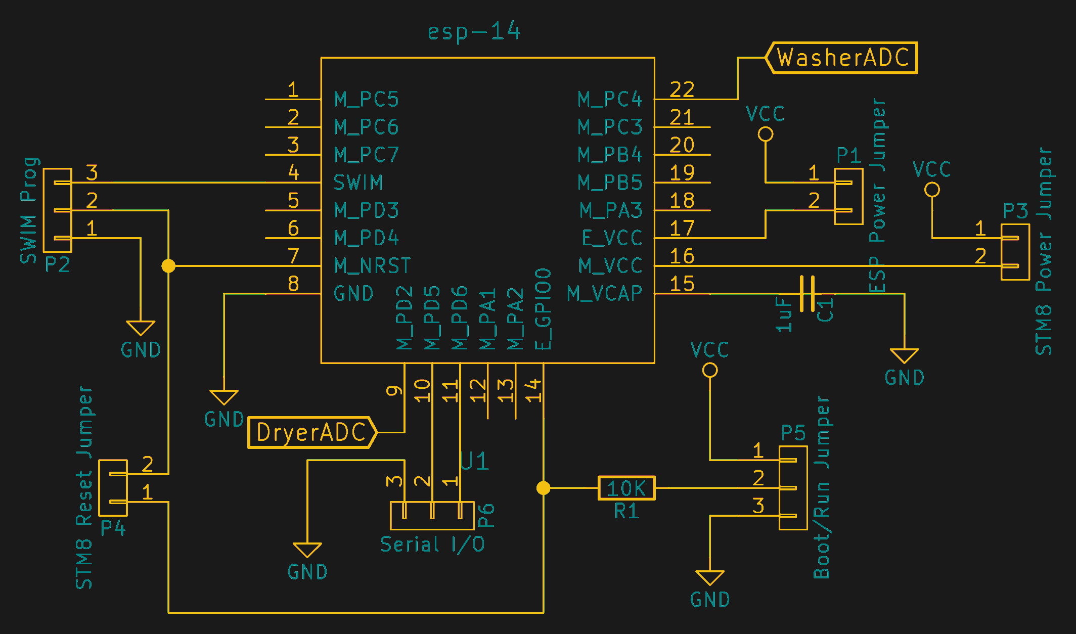 As shown in the schematic, there are jumpers everywhere in this project at the moment, but they’ve all come in handy, especially because the shared RX/TX lines make it hard to talk to one chip without the other overhearing or interrupting. For instance, to flash the ESP8266, you can disconnect power from the STM8, use the programming jumper to pull the ESP8266’s boot pin low, and then transfer in your software. To program the STM8, you can use either the SWIM interface, or disconnect the ESP8266’s power pin, switch up the TX and RX wires, and you’ve got a direct serial connection. And when running, with all the jumpers in place, everything works over the network. Sweet. If you wanted to build an ESP-14 breakout board, this would be a good place to start.
Other Hardware and Safety
I had two high-current current transformers in my junk box, so that was easy. Almost. Plugging in an old incandescent light bulb of known wattage, the transformer only put out a tiny signal, in the tens of millivolts. I added as many loops of thick copper wire from the appliances as I could fit into the beefy toroids, and that would just have to do. In the end, both the washer and dryer read about 500 mV peak-to-peak on the output of the transformers, so it’s easily readable with an ADC that uses a 3.3 V reference voltage, even if it’s not ideal. The right current transformers would help: they come in rated amperages if you buy them off the shelf. Plan ahead.
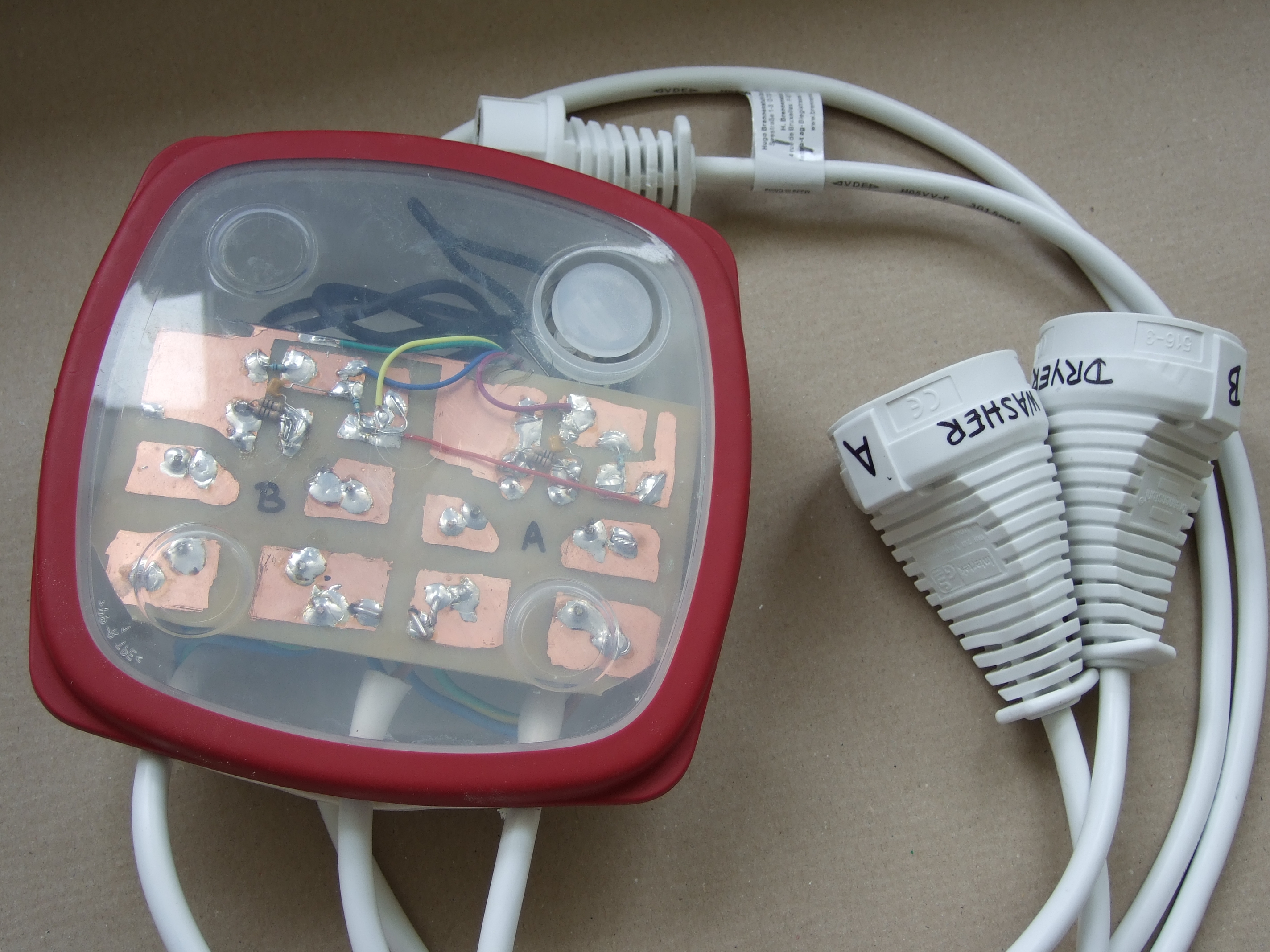 The mains-voltage portion of this project is sealed up entirely inside an IKEA sandwich box for “safety”. Since this was my first PCB-based project that I’ve built since moving to 230 V, I actually looked up the regulations, and allowed a bit more safety margin: 1 cm on the PCB between mains and any other pads. Two extension cables were sacrificed and soldered onto the PCB to provide one connection to the wall and one each for washer and dryer.
The outputs from the current transformers, and the 3.3 V supply for the ESP-14 snake out of the box for the low-voltage logic circuits. This is the one part of the design that gives me pause; if the high voltage ever works its way into the low-voltage wires, the ESP-14 on the outside of the box might become hot. I separated everything with as much air-gap as I could, and applied liberal amounts of hot glue to keep it all in place. Still, I’ll treat this thing with respect when I have to handle it. As it stands, it’s tucked away behind the washer anyway.
Since the signal from the current transformers is (low-voltage) AC, and symmetric about ground, a capacitor and voltage divider put the offset back into a reasonable range for the STM8’s ADC. I did this on the same PCB as the high-voltage circuitry, but in retrospect I could have done all of the low-voltage signal processing outside of the box. The PCB was a convenient module for testing on the bench with some lightbulbs and my oscilloscope during the transformer-prototyping phase.
Firmware
I wanted to do a peak detection in hardware with a diode and some capacitors, but the small voltage signal made that impossible, so I’m doing it in software.

The wires that come out of the sandwich box carry a voltage that’s centered about halfway between zero and 3.3 V, and makes a 50 Hz approximate sine wave. The amplitude of this sine wave is proportional to the current flowing through the washer or dryer. I’m not interested in the actual RMS power as much as simply knowing when the washer or dryer are running, so a peak-detection algorithm would work just fine.
A 50 Hz signal is ridiculously slow for an ADC that can pull off tens of kilohertz without breaking a sweat, so there’s a lot of room for oversampling and averaging here, which is good because the raw signal is fairly noisy. I tried a number of schemes, but the simplest of them was to take a sixteen-value exponentially-weighted moving average, and keep track of the maximum and minimum averaged values over two periods of the AC power cycle. The difference between the max and min is a great proxy for how much power the appliances are using. This is the value that gets sent to the MQTT broker.
MQTT
Since the esp-link software has an MQTT client inside, all that remains is to talk to it. It uses Serial Line Internet Protocol (SLIP), which might not be familiar to you if you haven’t done any dial-up networking since the 1990’s, but which couldn’t be simpler. In principle, you just tag a SLIP END character at the end of every packet. It can be nice to know when a packet starts too, so modern SLIPs simply put another END character at the beginning as well — packets of zero length are silently dropped. There’s also an escape and escaped versions of the escape and end characters, but I didn’t need them.
 Esp-link also uses a particular data format which is tailored to work well with C code and function pointer callbacks. It’s also got a CRC over the whole packet to reject conversations that accidentally look like a SLIP message. If you’re using C/C++ based code, including writing for Arduinos, there are libraries and examples that make it simple to communicate with MQTT/REST servers or over generic UDP and TCP sockets, and all this at the same time as it’s running the WiFi bridge.
To sum up the MQTT story, I needed to set up the data packets to match what the esp-link wanted, compute a CRC on the data, and then wrap it in the SLIP END characters. The STM8 then simply sends this out to the serial port at 115,200 baud and everything is groovy.
The complete firmware is divided up across a few Forth files. Have a look if you’re interested. The mqtt.fs file and power_meter.fs files have almost all of the user-useful vocabulary, and the rest is support. The end result is that something like mqtt.preamble washer.topic 42 message.value qos.and.retain send sends the number 42 (in ASCII) to the broker using the washer’s MQTT topic, quality-of-service level 0 and no retain flag.
Display
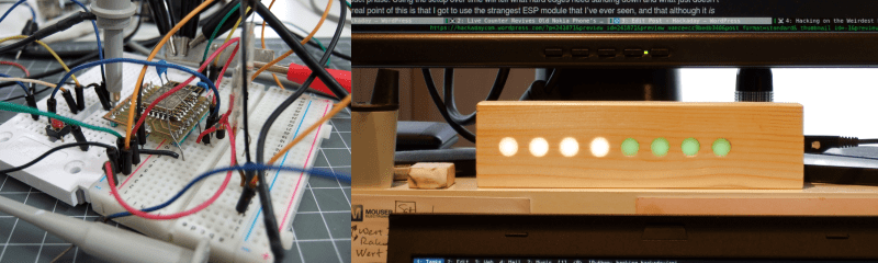
Wrapping the project up is a display that alerts us when the washer or dryer is done. For the moment, it’s a simple MQTT client built on a boring ESP-12 module that reads the washer and dryer topics from the broker and displays the data as a colored bar graph on a strip of WS2812 LEDs. It’s essentially a multi-LED version of the display node that I built up for this column on using MQTT with NodeMCU.
Inventions and Dimensions
The whole point of this project was to do something weird with a weird part. To that end, I think it’s a mixed success. The final device is quite pedestrian in this age of the connected home: a dual-channel power monitor that reports to the (local) cloud. But under the hood, it’s ridiculous.
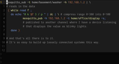 Half of that ridiculousness is thanks to [Thomas] for his STM8 Forth. And with the esp-link doing the heavy WiFi lifting as well as providing a remote reset, it’s a dream to work on the code remotely. In case you’re not sure how ridiculous this is, click that image to the right to watch me log in to the STM8, send arbitrary values, and then put it back into its default monitoring mode.
Of course you could just use the ESP-14 as it was intended: a pre-compiled C firmware running on the STM8 and using the stock AT-command firmware on the ESP8266. You could probably get exactly the same device built in just about the same amount of time, if you were familiar with the STM8 libraries. You’d have to write the MQTT protocol bits yourself, but that’s not actually all that hard for simple messages like these.
But there’s just an extra little bit of geek satisfaction in taking a module that makes very little sense, reflashing both chips inside, and cobbling together something odd but functional. I can telnet into a fifty-cent microcontroller in my basement and ask it how much power the washer is using. On port 23! How cool is that?
In truth, I hacked this together in a few hours of time spread out over a week, and just got it up to the minimum viable product phase. Using the setup over time will tell what hard edges need sanding down and what just doesn’t work. The real point of this is that I got to use the strangest ESP module that I’ve ever seen, and that although it is ridiculous, it can be useful. What would you do with a tiny little microcontroller strapped to an ESP8266 module?


I don’t recall TI ever offering an RPN calculator. HP did that. TI was always an algebraic notation supporter.
yep, they did, around the same time they had a great base conversion calculator that did Boolean operations.
black case, aluminium face, 7 segment LED bubble display, ran on a PP3 9V battery
The download link on the product page lives only a short time to prevent hot linking.
Not a remotely weird board. In fact, just what you want. The ESP is a power hungry beast, so keep it powered off unless it’s necessary, and use the frugal STM to watch IOs and housekeep. Et voila, decent battery life on your IoT device.
Battery issues aside, wherever there’s plenty of power available (like an easily accessible wall socket) I’d be tempted to do the inverse of what was done here, and make the smaller chip a transparent interface to all the GPIO. Then I could program the ESP however I like, with a firmware written in C, or interactively over the network with micro-python, and it would do all the heavy lifting.
Your idea’s a good one though, that I’ll have to remember it for later, since I’ve run into the fact that the ESP8266 is an absolute power hog when trying to put together small easily deployable sensors.
“I’d be tempted to do the inverse of what was done here…”
The original plan was to do a 3-fer: STM8 through ESP, ESP through STM8, and both cooperating. It ended up hard enough to get just one of the ideas done in a (still too long? how’s your attention span?) article.
But yeah! Buy one, do it, and shoot us an e-mail. I’d love to see projects made with this little thing.
So this would be good for monitoring systems like an alarm sensor or temperature sensor but not for a control type system. You could also use it for an update type system like a clock.
Depends on the ‘urgency’ of the control system. For something like a heating controller, having a quick look at the ‘cloud’ to see if there’s a new command only need be done every minute or so. For something like a light switch, it’d be no good though.
I would not like to have my heating system ‘cloud’ connected. It’s not something foreigners should play with.
So it’s good to see you recognising the hazards of mains, but the best thing to do is go read the UL standards. Creepage and clearance is a start, but you also need to use the right (UL-listed) components for anything safety-critical, i.e. for anything that separates between mains and something that a human might touch. Start with UL 62368.
The basic rule is that at least two completely independent things must fail before a hazard can exist.
Building a Class-I device (grounded) is pretty easy – you have a grounded metal chassis, and all user controls are also grounded. If something comes adrift inside the case, it will short to ground and blow a fuse or ELCB/RCD, and no one dies. For a Class-I device to become hazardous, the two necessary failures are of the grounding system and something else.
However, you have basically built a Class-II device, for which the rule is “double insulated”, i.e. there must be two formal steps of isolation between mains and the user. Proving that there are two isolations in all paths is a little difficult, so making a Class-II device as DIY is not the best idea. What you have built there is definitely non-conforming, though potting the mains portion in resin would go a long way towards making it safer. See UL-1310.
https://en.wikipedia.org/wiki/Appliance_classes
Also worth remembering that UL 60950-1 defines different classes of insulation, and the corresponding clearance creepage distances are different for the different classes, if an air-gap serves as the insulation.
For example clearance between active and neutral on the hot side of a SMPS board needs to be functional insulation, with less demanding requirements for hipot test, but the clearance between the hot side and cold side of an isolated SELV SMPS needs to meet a more demanding hipot standard – it’s “reinforced insulation” as per 60950. Between an active conductor and a switched active conductor, for example, the functional insulation requirement is much less fussy compared to the safety-critical hot-to-cold isolation barrier in a SMPS.
And it’s not just the PCB layout alone – to stay with the SMPS example, the transformer materials and winding insulation, the optocoupler, and any other component that straddles the isolation barrier must meet the same requirements for galvanic isolation strength, otherwise it’s completely moot regardless of how good your PCB layout is.
A current transformer would be another good example of this, because it also forms a safety-critical isolation barrier between a SELV system and the LV live circuit. (the insulation on the mains wire also plays a role.)
That current transformer (together with specified central wire with certain insulation) would also be “reinforced insulation”, with certain hipot test requirements, if you were taking a product to market.
The definition of “double insulated” is a bit complicated and hard to understand in some cases. An insulated wire within an insulated plastic box – sure, double insulated, that makes sense. But it’s also perfectly routine for line-powered consumer products to bring line voltage into a PCB in a moulded plastic enclosure. But there is line voltage on the pads on the bottom of the PCB, so it’s not double insulated, right? But it still is.
Good project, too.
Thanks for that! Great info for the US crew.
I’m in Germany, though. Your UL is useless to me, and we scoff at your puny 120V.
Which is to say, less sarcastically, traces have to be further apart, wires thicker insulated, and etc. I had to look stuff up to make sure I wasn’t doing anything stupid. I may have still made mistakes… It’s in a box. :)
He’s building a home built project. not a consumer device….
It does NOT MATTER; this issue was addressed in an earlier post on HackADay, and can be summarized as follows: if you build something which attaches to mains power, you are subject to all rules, regulations, limitations, stipulations, et al which govern ANY device built by any entity, for connection to mains power. Another way of saying this is that any HOME-BREW device you build belongs to the appropriate regulatory agency AS SOON AS YOU CONNECT IT TO THE MAINS.
“Originality is no excuse for ignorance.”–Fred Brooks
“Ignorance is eve less of an excuse for ignorance.” ~ Me
More to the point though, I’d be happier knowing that my home-built project was at least as safe as a consumer device.
W, with all due respect, the first thing I learned in Medical Appliances 101 was that the “grounded metal chassis” practice killed a lot of people (because of – surprisingly often – faulty ground contacts on the wall plug), and US connectors that expose wouldn’t
The method Elliot used, wireless transmission, is perfectly safe as long as no one opens the box. Fire caused by contact resistance is of some concern. Make sure the one plug that goes to the box can handle the load from the washer and the dreyer at the same time.
@Elliot: would it be possible to see the complete schematics? The PNGs on GitHub end at the analog header :-)
I am entertaining a similar project for my landlord, we have Speedqueen washer/dryer sets that are digital coin op machines…
The reason for the post is, there are open optocouplers on those machines, yea for me…
So you mite want to check for a service manual and or a schematic online. You mite find a paper envelope in the machine with a schematic that has the info… If your machines have mechanical timers then your solution is more universal and the way to go…
Many appliances here in the states have a service packet inside the machine, well I don’t work on any of the new stuff but I think it still applies…
So if anybody who don’t want to work with mains power, check for the optocoupler in the schematic, the Speedqeen has a Molex 2 conductor connector that I can interface to, probably used for auditing…
Also my schematic read that the opto transistor is off when the machine is on…
I hope the post is useful…
later
I was looking into doing something similar, maybe with some attiny micro. The idea would be of a “helper” for ESP that could do a few things, while the main code still was on the esp: more ADC channels, some PWM, some more wake up pins, some RTC that burns less current. But in the end, all the apps I built ended up requiring a more powerful micro so most code ended up on that.
I am actually surprised that there is no combination of arduino nano + esp module out there for very cheap from the usual sites, I have only seen it from expensive guys selling them for ~20, which is not that attractive considering you can have both for ~2 and need a couple of wires only to connect together.
Totally agree. I thought the Arduino WiFi was brilliant (Uno + ESP8266 tacked on) until I saw the price tag. It’s still easier/cleaner/faster than rolling your own solution, of course. But why nobody has made the obvious combo board baffles me.
Now that I think of it, the obvious way to do this _right now_ is to make an Arduino in a Wemos D1 mini form-factor. Or an UNO-shaped board with a spot to plug a D1 into it. Piggy-back on the power supply and serial port, add some extra pins out and pass as many of the ESP’s pins through as possible? You’d have an epic winner.
Whoever implements this and makes millions owes me a beer.
Something like https://www.aliexpress.com/item/Free-Shipping-Smart-Electronics-ESP-12E-WeMos-D1-WiFi-uno-based-ESP8266-shield-for-arduino-Compatible/32664054861.html you mean? (first hit, there are plenty)
No, that replaces the atmega328 with the esp.
Pretty much take one of the small arduinos and add an esp on it.
Darn, if you don’t do the coolest projects! Off the scale C^3 (Clear, Cool, Cheap ) Does you github archive contain the binary for the STM8 image? I wouldn’t mind a clearer picture of how you setup your breadboard, and the pcb cad files for the breakout you used? This is one I want to build for sure.
Woot!
The breakout for the ESP-14 is in Github, but it’s without the added extras — jumpers and power stuff. I should really make a board that adds the good bits — I did the schematic _after_ the protoboard wire-up, so there’s no layout for it yet.
I think I did include the STM8 Forth image in the repo. It’s not much different from the one at Thomas’s though (see the HaD.io link for STM8eForth.)
I have to say that the docs on this are kinda half-way. I don’t/didn’t really expect anyone to be re-building it. If there’s interest, I’ll clean stuff up.
Hej Elliot, great article! I’try this as soon as possible!
PS: I linked to your article in a HaD.io project log, and to your GitHub repository in the STM8EF Wiki :-)
PPS: thanks for the additional traffic – your HaD article caused a nice bump in the GitHub traffic stats :-)
That STM8S003 is actually a very good chip for the price – I’ve seen it as low as 15 cents, which is exceedingly cheap for any MCU, especially one with 8k flash, 1k ram etc, several timers, UART, I2C, ADCs,decent instruction set, internal R/C, etc. The price/performance ratio is superb, which is why I’m designing one in to a (very high volume) product right now – it’s much more capable than say an ATTiny and way cheaper. It’s a better cpu than an 8051 (ugh). There is a use case for hooking one up to an ESP – the ESP uses a huge amount of power when active, and if you only need it as a Wifi UART for occasional use, it’s fair enough.
It also runs over a fairly wide voltage range; about the only downside I’ve found it is doesn’t have an internal bandgap reference for the ADCs.
BTW something like 10 cents difference is very important when you’re doing low cost high volume stuff; for example right now I’m coding up an STM8 to replace both an EEPROM and an LED driver in a product, and it’ll save about 20 cents,or 2/3 of the chip cost – a very big deal. Plus I can get much better LED intensity resolution out of the STM8 than the LED drive its replacing, so the color fading is much smoother. The ultra-low-BOM end of the market is an interesting place to work.
@Dr.Tune: can I have one? I would really like to port STM8EF to it :-)
Huh? According to https://github.com/TG9541/stm8ef it’s fully working on the STM8S003F3P6 , which is what I’m talking about.
Sure, it will work on the STM8S003F3P6 out of the box. Some applications require board support code (e.g. custom character I/0).
What esp-link version are you using?
I tried to use your library with
esp-link v2.2.3 – 2016-06-21 21:58:48 – 1bcdc62
(on a mecrisp stellaris FORTH running on a STM32, but that should not hurt)
and it keeps crashing the esp-link connection.
I can ’emits’ ordinary strings from the stack, but when I do sth like
‘sync sync mqtt.washer $45 $46 $43 value’ I see no reaction.
Hiya! Haven’t looked at this codebase in 2 years. Oh my!
: value ( preamble topic n -- )message.value qos.and.retain send ;
Looks like you got it all right, except that “value” wants a single value to send, rather than three. It’s interpreting the $45 and $46 as the preamble and topic name respectively, and that surely doesn’t work right with ESP-link.
Try
sync sync mqtt.washer $45 value?Aha. Because esp-link’s SLIP/MQTT thing needs a special preamble and some byte-padding, I wrote that
message.valuefunction to take a single number, convert it to three ASCII characters, and then pack them into the right packet format.If you want to send, for example, three bytes of data, you’re going to need to look into the packet format. (Or just crib from my
message.offroutine which sends “off” and substitute in your three bytes instead of the ASCII letters “o”, “f”, and “f”.) These functions are all in messages.fs, and I vaguely remember that coding them up took me most of an evening, just to get the esp-link’s packet format figured out.