A Lightweight Two Metre Carbon Fibre Yagi Antenna

If you’ve ever cast your eye towards the rooftops, you’ll be familiar with the Yagi antenna. A dipole radiator with a reflector and a series of passive director elements in front of it, you’ll find them in all fields of radio including in a lot of cases the TV antenna on your rooftop.

In the world of amateur radio they are used extensively, both in fixed and portable situations. One of their most portable uses comes from the amateur satellite community, who at the most basic level use handheld Yagi antennas to manually track passing satellites. As you can imagine, holding up an antenna for the pass of a satellite can be a test for your muscles, so a lot of effort has gone into making Yagis for this application that are as lightweight as possible.

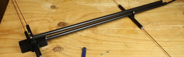
[Tysonpower] has a contribution to the world of lightweight Yagis, he’s taken a conventional design with a PVC boom and updated it with a stronger and lighter boom made from carbon fibre composite pipe. The elements are copper-coated steel welding rods, some inexpensive aluminium clamps came from AliExpress, and all is held together by some 3D-printed parts. As a result the whole unit comes in at a claimed bargain price of under 20 Euros.

This antenna is for the 2 M (144 MHz) amateur band, but since it’s based on the [WB0CMT] “7 dB for 7 bucks”  (PDF) design it should be easily modified for other frequencies. The 3D printed parts can be found on Thingiverse,  and he’s also posted a couple of videos in German. We’ve posted the one showing the build below the break, you can find the other showing the antenna being tested at the link above.

Continue reading “A Lightweight Two Metre Carbon Fibre Yagi Antenna”

Vintage Laptop Keyboard Types Again Through USB

Have you ever had a laptop you just wish you didn’t have to retire when its specification becomes to aged for your needs? Wouldn’t it be great if you could upgrade it and keep using the physical hardware!

[Alpinedelta] has a vintage Toshiba T1000 laptop, roughly a PC-XT clone from the late 1980s. Its 80C88 processor, CGA display, and 512k of memory make it a museum-piece, but he has plans to modernise it using a LattePanda Intel Atom based single board computer.

To make that happen, he has to ensure all the Toshiba’s peripherals will talk to a modern host. Unfortunately back in the 1980s many PC clones were clones in a rather loose sense, and especially so in the laptop arena. Thus there are no handy standard PC interfaces and since USB was several years away at the time, nothing the LattePanda can talk to directly. His solution for the keyboard is to wire its matrix directly to a Teensy microcontroller that then provides a USB interface, and he’s put up a useful step-by-step Instructables guide.

There is no standard for a laptop keyboard matrix, so the first and most tedious task is to unpick its layout.This he did by identifying each trace and assigning a different rainbow colour to it, before noting down which keys appeared on it and collating the results in a spreadsheet. The different colours of wire could then be assigned to the colours of a piece of rainbow ribbon cable, and wired in sequence to the Teensy’s I/O pins. There then follows a step in the software in which he assigns the pin mappings to the lines in his spreadsheet, then the sketch can be compiled and uploaded to the Teensy. Result: a vintage keyboard now talking USB.

Using a Teensy to present a USB keyboard to the world is a well-worn path, we’ve seen it with both newer keyboards and other relics like this one from a DEC VT100.

Thanks [Brent] for the tip.

It’s A Synthesizer. It’s A Violin. It’s A Modulin

It sounds a little like a Theremin and looks a lot like the contents of your scrap bin. But it’s a unique musical instrument called a modulin, and after a few teasers we finally have some details on how it was built.

Making music with marbles is how we first heard of [Martin] of the Swedish music group Wintergatan. He seems as passionate about making his own instruments as he is about the music itself, and we like that. The last time we saw one of his builds was this concert-ready music box, which he accompanied with an instrument he called a modulin. That video gave only a tantalizing look at this hacked together instrument, but the video below details it.

“Modulin” comes from the modular synthesizer units that create the waveforms and pressure-sensitive ribbon controller on the violin-like neck. The instrument has 10 Doepfer synthesizer modules mounted to a hacked-together frame of wood and connected by a forest of patch cables. [Martin]’s tour of the instrument is a good primer on how synthesizers synthesize – VCOs, VCAs, envelope generators, filters – it’s all there. We’re treated to a sample of the sounds a synthesizer can make, plus majestic and appropriately sci-fi sounding versions of Also sprach Zarathustra and the theme from Jurassic Park. And be sure to check out the other video for another possibly familiar tune.

This might be old hat to musicians, but for those of us to whom music is a mystery, such builds hold extra sway. Not only is [Martin] making music, he’s making the means to make music. We’re looking forward to hearing what’s next.

Continue reading “It’s A Synthesizer. It’s A Violin. It’s A Modulin”

Dummies Guide To Reverse Engineering

[Juan Carlos Jiménez] has reverse engineered a router — specifically, a Huawei HG533. While that in itself may not sound substantial, what he has done is write a series of blog posts which can act as a great tutorial for anyone wanting to get started with sniffing hardware. Over the five part series, he walks through the details of identifying the hardware serial ports which open up the doors to the firmware and looking at what’s going on under the hood.

The first part deals with finding the one or several debug ports on the hardware and identifying the three important pins – Rx, Tx and GND. That’s when he shows novices his first trick – shining a flashlight from under the PCB to find the pins that have trace connections (most likely Rx and Tx), those that don’t have any connections (most likely CTS and DTR) and those that have connections to the copper pour planes (most likely VCC and GND). The Tx signal will be pulled up and transmitting data when the device is powered up, while the Rx signal will be floating, making it easy to identify them. Finding the Baud rate, though, will require either a logic analyser, or you’ll have to play a bit of a guessing game.

Once you have access to the serial port and know its baud rate, it’s time to hook it up to your computer and use any one of the several ways of looking at what’s coming out of there — minicom, PuTTY or TeraTerm, for example. With access to the devices CLI, and some luck with finding credentials to log in if required, things start getting interesting.

Over the next part, he discusses how to follow the data paths, in this case, looking at the SPI signals between the main processor and the flash memory, and explaining how to use the logic analyser effectively and decode the information it captures. Moving further, he shows how you can hook up a USB to SPI bridge, connect it to the flash memory, take a memory dump of the firmware and read the extracted data. He wraps it up by digging in to the firmware and trying to glean some useful information.

It’s a great series and the detailed analysis he does of this particular piece of hardware, along with providing a lot of general tips, makes it a perfect starting point for those who need some help when getting started on debugging hardware.

Thanks, [gnif] for posting this tip.

Continue reading “Dummies Guide To Reverse Engineering”

How To Receive Pictures From Spaaace!

The International Space Station, or ISS, has been in orbit in its various forms now for almost twenty years. During that time many of us will have stood outside on a clear night and seen it pass overhead, as the largest man-made object in space it is clearly visible without a telescope.

Most ISS-watchers will know that the station carries a number of amateur radio payloads. There are voice contacts when for example astronauts talk to schools, there are digital modes, and sometimes as is happening at the moment for passes within range of Moscow (on Feb. 14, 11:25-16:30 UTC) the station transmits slow scan television, or SSTV.

You might think that receiving SSTV would be hard work and require expensive equipment, but given the advent of ubiquitous mobile and tablet computing alongside dirt-cheap RTL-SDRs it is now surprisingly accessible. An Android phone can run the SDRTouch software defined radio app as well as the Robot36 SSTV decoder, and given a suitable antenna the pictures can be received and decoded relatively easily. The radio must receive 145.8MHz wideband FM and the decoder must be set to the PD120 PD180 mode (Thanks [M5AKA] for the update), and here at least the apps are run on separate Android devices. It is possible to receive the signal using extremely basic antennas, but for best results something with a little gain should be used. The antenna of choice here is a handheld [HB9CV] 2-element beam.

A failed grab from a 2014 transmission, proving that Hackaday scribes don't always get perfect results.
A failed grab from a 2015 transmission, proving that Hackaday scribes don’t always get perfect results.

You can find when the station is due to pass over you from any of a number of ISS tracker sites, and you can keep up to date with ISS SSTV activity on the ARISS news page. Then all you have to do is stand out in the open with your receiver and computing devices running and ready, and point your antenna at the position of the station as it passes over. If you are lucky you’ll hear the tones of the SSTV transmission and a picture will be decoded, if not you may receive a garbled mess. Fortunately grabs of other people’s received pictures are posted online, so you can take a look at what you missed if you don’t quite succeed.

Even if you don’t live within range of a pass, it’s always worth seeing if a Web SDR somewhere is in range. For example this Russian one for the current transmissions.

In that you are using off-the-shelf hardware and software you might complain there is little in the way of an elite hack about pulling in a picture from the ISS. But wait a minute — you just received a picture from an orbiting space station. Do that in front of a kid, and see their interest in technology come alive!

Hacking On The Weirdest ESP Module

Sometimes I see a component that’s bizarre enough that I buy it just to see if I can actually do something with it. That’s the case with today’s example, the ESP-14. At first glance, you’d ask yourself what AI Thinker, the maker of many of the more popular ESP8266 modules, was thinking.

The ESP-14 takes the phenomenally powerful ESP8266 chip and buries it underneath one of the cheapest microcontrollers around: the 8-bit STM8S003 “value line” chip. Almost all of the pins of the ESP chip are locked inside the RF cage’s metal tomb — only the power, bootloader, and serial TX/RX pins see the light of day, and the TX/RX pins are shared with the STM8S. The rest of the module’s pins are dedicated to the STM8S. Slaving the ESP8266 to an STM8S is like taking a Ferrari and wrapping it inside a VW Beetle.

I had never touched an STM8 chip before, and just wanted to see what I could do with this strange beast. In the end, ironically, I ended up doing something that wouldn’t be too far out of place on Alibaba, but with a few very Hackaday twists: a monitor for our washer and dryer that reports power usage over MQTT, programmed in Forth with a transparent WiFi serial bridge into the chip for interactive debugging without schlepping down into the basement. Everything’s open, tweakable, and the Forth implementation for the STM8S was even developed here on Hackaday.io.

It’s a weird project for the weirdest of ESP modules. I thought I’d walk you through it and see if it sparks you to come up with any alternative uses for the ESP8266-and-STM8S odd couple that is the ESP-14.

Continue reading “Hacking On The Weirdest ESP Module”

Unconventional Homopolar Motor

As a hacker, chances are that you have built a homopolar motor, as you only need three things: a battery, a magnet and some copper wire. There are zillions of videos on YouTube. This time we want to show you [Electric Experiments Roobert33]´s version. Definitely a fresh twist on the ubiquitous design that you see everywhere. His design is a bit more complicated, but the result makes the effort worthwhile.

regla_mano_derecha_laplace
Right hand rule for the Lorenz force. By Jfmelero, via Wikimedia Commons

The homopolar motor was the first electric motor ever built. Created  Michael Faraday in 1821, it works because of the Lorentz force. This force acts on any current-carrying conductor that is immersed in a magnetic field which is perpendicular to the current. These motors really have no practical applications, but are an excellent way to learn basic aspects of electromagnetism.

In this setup, there are two conductive rings placed above a wooden base, connected to the battery terminals. Neodymium magnets are connected by a conductive rod that pivots in the center of the rings, closing the circuit and allowing the flow of current. Then the Lorentz force makes its magic and pushes the rod and magnets in a circular motion.

Very clean and well-edited work, as are other videos by [Electric Experiments Roobert33]. You may want to replicate this nice motor, or you can also make the simpler version to start experimenting.

Continue reading “Unconventional Homopolar Motor”