Even if you’re reading this on a piece of paper that was hand-delivered to you in the Siberian wilderness, somewhere someone had to use energy to run a printer and also had to somehow get all of this information from the energy-consuming information superhighway. While we rely on the electric grid for a lot of our daily energy needs like these, it’s often unclear exactly how the energy from nuclear fuel rods, fossil fuels, or wind and solar gets turned into electrons that somehow get into the things that need those electrons. We covered a little bit about the history of the electric grid and how it came to be in the first of this series of posts, but how exactly does energy get delivered to us over the grid?
Generation
It all starts at the power generating station. Whether this is a wind turbine, a diesel generator, a jet engine, or a nuclear power plant, the idea is the same: a generator must spin. Wind can blow it, an internal combustion engine can turn it, or a heat source can make some steam to drive a turbine which then spins it. (One notable exception is a solar panel which generates DC, then uses an inverter to turn that energy into AC for the grid.) Either way, once the generator is spinning then the energy begins to flow out onto the grid.
There are a few different types of power plants as well. Some power stations are good at producing a constant, large amount of power all of the time but aren’t too good at changing their output to meet demand. Nuclear stations and combined cycle combustion turbines are good examples of these “base load” plants that produce power for the constant load on the grid. Since power is consumed instantly after it’s produced, however, it’s important to keep up with the demand so that the grid’s voltage and frequency remain constant. For times with increased demand on the electric grid, such as mid-afternoon in the summer when everyone’s air conditioners start working full time, peaking power plants are brought online. Often these are single cycle combustion turbines, diesel generators, or hydroelectric plants. These plants are good at starting and stopping when needed unlike large base load plants cannot be easily started or stopped.
There are other generating stations that don’t fall into either category, most importantly some renewable resources. Part of the problem with wind and solar energy is that their energy production doesn’t align with energy demand. Sadly, the wind isn’t always blowing when people need to run air conditioners or start up a manufacturing facility. This is the reason why improved battery technology could be a huge boon to renewable energy. If solar and wind energy could be stored, these generation facilities could be used as true peaking power plants and maybe eventually base-load plants.
Transformers
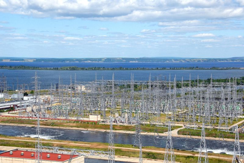
Wherever the energy comes from, the electricity from a typical power plant will be a lower voltage (generally somewhere around 10 kV) for a large generator, for a few reasons. First, low voltage is safer and easier to work with. Second, it’s cheaper to insulate low-voltage circuits. Since the windings of a generator are essentially just a whole lot of wire, a generator will be less expensive if its windings don’t need a lot of insulation. To get the energy delivered long distances on power lines in an economical way, however, the voltage needs to be much higher, often in the range of 100-500 kV. To bridge the gap between the low-voltage generators and the high-voltage power lines, the energy is sent through a step-up transformer in a substation (or “switchyard”) near the power plant. Similar to how a vehicle’s transmission uses gears to trade speed for torque, a transformer trades voltage for current. The high-current, low-voltage electricity from the generator is “transformed” into low-current, high-voltage electricity which can now be shipped out of the power plant.
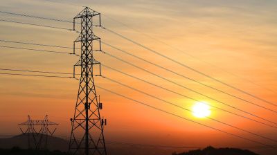
The high-voltage wires that leave the power plant’s substation are called transmission lines. These are the largest of power lines, often on huge towers or poles and with no customers attached as almost all transmission lines connect substations with other substations. Transmission lines are the backbone of the power grid and without them we’d be stuck with small, Edison-style local grids with a power plant on every block.
Three Phases
All of this might seem like a lot of effort just to ship some electricity around, but the long distances often involved make it essentially the only economical option since power losses go up with the square of the current. This means that if the current on any particular wire can be halved (by doubling the voltage through a transformer), the resistive losses will be four times lower.
While it’s not immediately obvious, transmission lines are always in sets of three. Generally they will also have a smaller ground wire for lightning protection. Each wire carries one “phase” of electricity. Most of the world has settled on a three-phase system because it’s the most efficient way of getting as much power delivered with the least amount of wire. It also puts less stress on generators and motors than a two-phase system would. Each phase is at the same voltage, but is at a different point in its rotation. This means that while one phase is at is peak, the other phase is one-third of a period behind and the other is one-third of a period ahead. Although somewhat difficult to wrap one’s mind around at first, what it means in practice is that there is more voltage available between either two of the phases than from a single phase to the neutral or ground wire, and that its a much more efficient way of running large motors than using a single phase.
While three-phase power is useful for industry, small motors like the kind used in refrigerators, air conditioners, and ceiling fans run just fine on a single phase of power. Other loads such as electronics convert AC to DC anyway, so they also run well with only one phase. This is why almost all residential users on a grid are fed one single phase of power. In the United States, at least, the phase is split in half from a center-tapped transformer which is why there are two wires leading to a typical house. The voltage between the two are 240 volts, and 120 volts from either wire to the center-tap of the transformer. The wires are often incorrectly called “phases” but a better term would be “taps” or “legs” since splitting a phase isn’t the same as having two phases as the taps or legs still have the same phase angle.
From power plant to the home, the grid is fairly simple on the surface. When it gets to the size of an entire country, though, it’s not as straightforward. Power can flow and interesting ways and as we’ll investigate in the next article, sometimes the entire grid can collapse.


why is it called single phase when it uses 2 wires? if ac reverses direction many times a second why doesn’t the neutral shock me?
The neutral will shock you if you touch it and a hot leg at the same time. The neutral is bonded to ground in the system. I’m not sure about other countries, but in the US it’s typically done at the distribution transformer, at the meter base, or in the breaker panel.
If you are touching ground and you touch the neutral, you typically won’t get shocked because the neutral sits at ground potential in a properly operating system. But because the neutral and ground are both normally at the same potential, touching a hot and a neutral or touching a ground and a neutral will cause a shock.
“The neutral is bonded to ground in the system. I’m not sure about other countries, but in the US it’s typically done at the distribution transformer, at the meter base, or in the breaker panel. ”
Or in some installations, a combination of those… and maybe even a cold-water pipe ground.
Was building a Sprint cell site in a suburb of Los Angeles and the local regulations required a cold-water pipe ground as the primary site neutral / earth ground but Sprint required a ground rod placed at the meter / service disconnect point, as did SoCal Edison; neither the client nor utility wanted the cold-water ground. SCE even went so far as to state they wouldn’t set the meter if CWG is in place because, as they put it, the voltage potential difference between the CWG and meter ground could alter the metering and would accelerate galvanic corrosion to the pipes. So we installed everything but didn’t connect the SCE ground, so we could get building inspection passed and permission to call for meter set, then removed the CWG and connected the rod at the meter for SCE to be happy. 15 years later and the site’s still in place and carrying significant traffic.
-It’s a abuse of language when we call the live wire : phase.
– The neutral is wired to earth at the electrical substation. ( https://scottiestech.info/wp-content/uploads/2009/05/electric_hookup_okay.jpg )
Neutral must also be bonded to earth at the customer’s service entrance for ground-fault protection to work properly.
This sounds very fishy. A typical ground fault circuit interrupter does not require a ground connection to operate properly, so it should not even care which line is neutral or hot: it can’t tell. So it certainly can’t tell whether one of those lines is connected to earth back at the entrance.
A GFI absolutely requires a ground connection to operate properly. It just doesn’t need the ground connection to be through itself. The ground connection that is really needed is the one being discussed, at the distribution transformer.
That’s the only way a ground fault path can exist, is if the current has a path from a energized conductor back to the source, which would be through that main system ground bond. If that ground connection didn’t exist, then a grounded human touching an energized conductor would not form a circuit since the ground isn’t connected to the system anywhere else.
I see your point. A GFCI just measures the difference between the outgoing and returning current, and interrupts the circuit if there is a current imbalance. Though the GFCI device itself requires no ground, and doesn’t care which line is hot or neutral, the imbalance won’t occur unless there is an alternate return path for the current, and that fault path through the unsuspecting human would not exist if both supply lines were left floating.
Geez, put it that way and it sounds like we’re idiots for grounding any part of the power supply :-)
I think you both are saying the correct thing but from different perspective.
I you have a standard GFCI outlet with Grn Wht Blk wires going to it, the thing will actually trip correctly even if the electrician forgot to connect the Grn (Ground) wire. The GFCI compares the current on the Blk (Hot) and Wht (Neutral) wires and if not precisely the same it assumes the imbalance to be a fault and trips the built-in breaker (in the GFCI) to isolate the circuit.
Imagine someone sticking a fork into a powered up toaster. The toaster heater coil is electrified and touches the metal fork then the idiot’s hand, and then thru his belly button to the edge of the metal trim on the grounded dishwasher. FAULT! TRIP! LIFE SAVED!
That said, if you stood on a isolating wood stool, and plugged a defective line cord into the GFCI outlet, and with one hand touched the Wht (Neutral) and with the other hand the Blk (Hot) wire, the GFCI sees no fault (currents are balanced), and you are electrocuted. The house circuit breaker panel might, trip (too much current >15A), but the GFCI is happy.
I’ve always been bothered by the fact many diagrams indicate a literal ground-to-Earth as the real system “ground”. Grounding rods (plural) are required by NEC and must be bonded to the breaker panel, but for basic understanding of home wiring, it only confuses things.
For the sake of most discussion, fault current never flows through Earth ground. For example, the ground rod is not the return path to the center-tapped transformer… the neutral is, thus being the reason ground is bonded to neutral at the breaker panel the service entrance feeds. Ground/neutral bonding doesn’t apply to subpanels as the neutral wire should never carry fault current.
Umm electricity takes ALL paths to ground. Your ground in your house does MOST of the heavy lifting when a ground is needed.
For the sake of discussion fault current DOES flow through the earth ground. The ground rod IS the same circuit as the center tap of the transformer, IF you understand circuits this can simply be imaged as multiple wires going to the ground plane.
If YOUR panel didn’t handle the fault current then the entire wire back to the transformer could possibly handle the fault load simply acting as a 300+meter heating wire. Thus burning down your house and the transformer.
@benchie…
I agree, electricity takes all paths to ground. However, the ground rod should be modeled as a resistor with very high resistance because it’s a copper plated piece of steel pounded into soil. There’s another Earth ground coiled on the bottom of the pole at the street. You can’t tell me that the 500ft of dirt between my house and the road is carrying a significant amount of current during a fault. The neutral wire from the transformer is the primary ground because it is directly connected to the panel and by far the lowest resistance path for current to take. The two paths are the same circuit, but in circuits with parallel resistors of differing values, more current flows through the resistor with a lower resistance… in this case, an actual wire, not dirt. You’re right, though, the wire would heat up and possibly burn the house down IF the full rated current for the service created a fault and the protection device at the pole failed. Typical fault current results from a short in a single circuit that’s likely to only be a 15 or 20 amps circuit.
A good earth is always important –
https://cdn.hackaday.io/images/3196641487386373403.jpg
Had a teacher that bet up that he could hook a ground rod straight to an outlet and not trip a breaker. I’ll be darned if he wasn’t right, pulled less than five amps when dry, he said he’s seen a max of 12amps after a good rain storm, started steaming.
At 120 volts the ground isn’t a good conductor. Even at 220. It when you get up to lightning levels of voltage that the electrons start flowing, which is what a ground rod is really for. Also why pool pumps and hot tubs are grounded as close as possible.
The hot wire carries the electric potential, and fluctuates between positive and negative ~ 50-60 times a second. the neutral wire exists to complete the path and does not have an electric potential of its own.
a potential is always defined to a reference. A better formulation is: the hot wire (phase) has a potential of … with reference to the neutral. The neutral is defined as zero potential.
At the end of the 19th century many power stations produced 2-phase electricity, with typical frequencies of 40 Hz.
As a matter of curiosity: It is possible to convert e.g. two-phase AC into three-phase AC by means of a transformer.
Some European railway companies (CH, D, DK, S, N) use one-phase AC with a frequency of 16.7 Hz (before 16 2/3 Hz). In Switzerland two railway companies still use three-phase AC.
The neutral wire doesn’t have ‘an electric potential of its own’ – but ONLY with respect to ground, and ONLY if the neutral wire is connected to ground – which is the very definition of a ‘neutral’ wire. The neutral wire DOES very much have an electric potential of its own with respect to the hot wire. The ONLY difference between neutral and hot is that one has a ground connection and the other does not.
There is an instance where the neutral will shock you. If you break a neutral connection between a functioning device such as a light fixture and the panel and touch both the device and panel sides of the neutral the current will flow through you to complete the path. Many a first year electrician has discovered this the hard way.
Ditto,— though in the USA if the neutral is broken there could be 240 volts across your devices…
As noted above, most homes in USA have two hots an a neutral, a balanced load will have zero volts on the neutral
the neutral only carries a load when there is an unbalance load witch is all the time, leg a 10 amp load leg b 5 amp load the neutral will carry 5 amps…
If both legs carry 10 amps then 0 amps on the neutral…
To an electrician this is known as a network, 2 hots an a neutral again in USA…
later
I work as a Transmission Engineer for a big power utility in the states and all I can say is: what a perfect piece of writing!
I doubt that jet engine is used in a power plant. I think the writer think about gas turbine… as the link is referencing in the wikipedia.
Though most of the jet engines are basically a modified gas turbine
Some of the smaller plants do indeed use jet engines, usually ones that are no longer airworthy but are still otherwise good but others are purpose-built to do other things than power an aircraft. If one digs around on YouTube, there are several videos of former aircraft turbine engines being modified for ground use, as well as them being tested.
Occasionally, some plants will run large ‘frame engines’ to generate a consistent base-load, and smaller, converted jet engines to provide for varying load capacity since the smaller engines can be brought online and taken offline much more quickly.
Usually these gas turbines are related to aircraft engines by having a common core, but have been purpose built for fixed service. Or in some cases, marine use.
GE supplies remaunfactured engines for this service. One local plant has one that came out of an F-18 for combined cycle cogen service.
Some components for that unit may have flown, but if it came out of an F-18 it was remanufactured and certified as a General Electric LM1600 which is the industrial and marine gas turbine version of the GE F404 aircraft engine series. While they share a common central core with casings and rotating parts that are the same, these are very different engines. It might have been good PR for the local plant to assert that their new gas generator came from a fighter, the truth here is far more complicated.
I worked in the industry for decades.
The are and are called aeroderivative gas turbines. Look at manufacturers like GE and RollsRoyce. They are smaller than traditional gas turbines but have very high efficiencies and lower emissions.
They are not really smaller, they just don’t have a high-bypass fan on them or the ducting. The core is the same size for both the fixed and flying models.
One great advantage of three-phase power is that smoothing capacitors are not required when it is rectified to DC, as the rectified voltage never approaches zero like it does in a single-phase system. The ripple is just a few percent: perfectly adequate for running a DC:DC converter with minimal line-side filtering.
A three-phase supply also enables really neat tricks like using a cycloconverter to synthesize other frequencies directly for the purpose of variable-speed motor drives, without the need of an intermediate filtered DC bus. (Think mine elevators or conveyor belts.)
The power is not consumed instantaneously, there is this little delay called the speed of light. (In copper, it is slower than vacuum.) Also some power is stored in the tuned circuit known as the power grid.
The relevant speed is actually the speed of light through the air (and/or the insulating materials around your power wires – they’re in the air for most of the distance between my house and the power station).
> This is why almost all residential users on a grid are fed one single phase of power.
This may (or may not) generally apply to the NA region but that’s definitely not correct for e.g. most European countries. You’ll have to search really hard to e.g. find a German house receiving only one phase.
“While it’s not immediately obvious, transmission lines are always in sets of three.”
I have seen small towns surrounded by many many miles of woods in Canada that had a single wire feeding them power. They used the earth as the return path.
For telegraph, maybe. For power, certainly not. Resistance of the ground is too high and unpredictable for this to work.
Yeah, sounds kooky, but it’s not. Plenty of examples exist.
https://en.wikipedia.org/wiki/Single-wire_earth_return
Thank you Sir. Now I have seen everything.
My brothers neighbour uses a single wire with ground return. ( my brother is off grid )
The intricacies of the power grid are quiet profound. The ability to maintain frequency and voltage with a quiet a large varying load fed from multiple generators in different parts of the continent/country/state is quiet amazing
OMG! It says the Earth (or sometimes a body of water) is used as the return path.
Better post signs! I’ll look for wires, dead fish, and lines of telephone poles ending at the water from now on!
When I was a kid seven of us were playing in the lake and lightning struck on the other shore a good 5 K away and we all felt the shock and screamed at the same time. It was a swift approaching storm because it was bright and sunny on our side.
In the beginning of electrical technology many power stations used a two phase system. It is even possible to convert m-phase to n-phase (n, m >1) by means of a transformer.
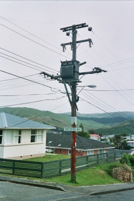
This isn’t a transmission line, then; this is almost definitely a distribution line.
Main Transmission lines are in sets of three. Distribution systems the can either be single phase or three phase based on the consumer needs.
The wires are often incorrectly called “phases” but a better term would be “taps” or “legs” since splitting a phase isn’t the same as having two phases as the taps or legs still have the same phase angle.
Actually the the “legs” of a 120/240 center tapped transformer are 180 degrees out of phase from each other.
Right. If they were in phase, the voltage between them would be 0, not 240.
I find this sentence confusing: “In the United States, at least, the phase is split in half from a center-tapped transformer which is why there are two wires leading to a typical house.”
Every home I’ve seen, including my own, has three wires leading to the house that feed into and out of the electric meter and into the breaker panel. These three wires consist of two half windings (both hots) and the center tap itself (neutral) from the center tapped transformer on a pole near the road. That allows 120V and 240V circuits to be created.
Very often when talking about electrical wiring, the bond wire is omitted. A piece of typical household Romex for instance, would be referred to by most electricians as 12-2, meaning #12 AWG, 2 conductor. The bond (ground) wire is assumed to be there.
In other words, the author is technically correct in saying that American homes are typically fed with 2-conductor wire, though I can certainly see why this could be confusing.
Lazy electricians, I suppose. ;)
“Romex” is available as 14/2 and 12/2 (among other sizes), both with and without the ‘bond’ wire. They are differentiated in name as “14/2″ and 14/2+G”, for instance, without and with ground/bond wire, respectively.
Lazy perhaps, but I know that when i walk into my local electrical supplier and ask for 14-2 Romex I’ll be handed a roll of Romex brand cable containing two #14 AWG conductors with THHN insulation and an non-insulated bond wire. The only time I would need to specify anything to do with the bond is if I needed a roll of wire without it.
Also, I wasn’t trying to insinuate that Romex only comes in 12-2. I was simply using that as a specific example.
@Bryan Cockfield,
Nice Overview of public power grids. Maybe for a follow-on article, a couple of suggestions:
1. Discuss how the frequency of the mains-power is an indicator of how the grid is using power and where. Many people think the “line frequency” is a “reference”. It is NOT. In-fact the mains frequency (50 or 60 Hz) is a key indicator of power delivery from rotating machines (e.g. Generators). Efforts are made by the power providers to keep the line frequency constant (even by synchronizing the generation frequency to GPS stabilized clocks), but the effort is typically not perfect – and this imperfection provides information on how much power is being delivered.
2. Describe how the concept of Power Factor Correction (PFC) is handled at various load points, especially at large industrial users where there can be impressive amounts of hardware to correct both long-term PFC (e.g. capacitor banks and/or rotating machines), and dynamic PFC (large rooms with coupled capacitors and inductors).
The power factor thing is interesting. I was an electrician in the Navy. I worked with another electrician that had been an electrical engineer in the Philippines before he enlisted in the US Navy. He worked for a power company.
He put in a suggestion to the Navy that they install some capacitor banks to counteract all the inductive equipment that had been added after the power plants were designed. He even showed the calculations for how much fuel they would save generating power. They basically patted him on the head in a very patronizing way. They lost out on a very good idea.
I suspect the upcoming dissertation will explain it clearly as this is some darn fine writing so far!
Last time this came up the subjects of phase lead/lag for control of direction and magnitude of power transfer, plus the occasional 50/60 Hz freq. corrections shifts over a long period to keep the overall average (as some devices depend on cps for timekeeping), created multiple debates that rose more like a battle scene out of the recent Planet of the Apes movie than any discussion. Cries of old way vs new, never got separated… but both belonged. The subject of grounding also resulted in much chest-beating in that same discussion, and is already showing signs of same here. Some things that have been said are… err… simply shocking!
There’s been a LOT of progress and change in technique since the CME took out parts of the Eastern grid and got the industry’s attention… and that event has been studied by universities that worked with the industry to update the grid, increase reliability, make changes… I’m very interested in what was learned and that is applied now.
If any debate arises… it would be best spent on another Carrington Event. Or perhaps on the X28 flare of not too terribly many years back.
I think a discussion addressing CME impacts and what steps have been taken since the CME-induced geomagnetic storm grid collapse in 1989 would be fascinating.
Other than close monitoring of the Sun and hopes that early warnings will prompt defencive deenergization of vulnerable lines, precious little from what I can see.
“Close monitoring of the Sun…”. Yes they are! And you peek over their shoulders and watch. Google N3KL and SolarHam or SpaceWeather for everything you need. Side benefit is you’ll be alerted when Aurora may be visible from your back porch. Better yet, look up how to build your own magnetometer with just a small laser, string, and a magnet so you know when to step outside and look up. Can be sensitive enough to let you know when the neighbor parks their car in the driveway or the kids open the fridge.
Back to the grid: The Carrington Event is worthwhile to study. Happened well before there was any power grid. Just a quick read will give you descriptions of telegraph wires melting, the drippings lighting fires that destroyed buildings, and telegraphs that continued to operate despite the operator disconnecting the battery supply. Caution: Could make a prepper outta you!
An event of the magnitude of Carrington one would cause significant damage in any number of domains, the grid being one of the few that could prepare itself such that the damage might be limited. The satellite fleet would not be so lucky nor would other exposed equipment. While it might not take down civilization as we know it, the impact would be profound, and few would be left untouched.
“Ground” on a planetary scale is not just simply 0 volts at all points. The Earth has a DC potential formed by the solar wind streaming through the atmosphere, in one pole, through the planet, out the other pole and through the atmosphere again. That current is enough to make the very atmosphere glow where it flows into and out of the planet, AKA aurora. The DC amperage is of a magnitude such that we will likely never have a conductor that could survive it, and any current flow across a resistance produces a voltage. Hence Earth’s ground potential in Florida is not the same voltage as in Connecticut. Ground for you at home is still 0v for practical purposes, but for the utilities it is different potentials everywhere and thinking has had to change. Ground is not quite the ground you were taught… Bet can measure this voltage during even a minor solar storm with just a few hundred feet of wire and dvm!
As for the ’89 solar event, hopefully accurately recalling some reading, the solar storm produced aurora and DC ground current. The distribution design allowed DC into the AC distribution system through grounded transformer taps and that DC flow added to the AC load pushed a “breaker” beyond limits and it popped, even though the AC Ammeters indicated they were within limits. Other segments had to pick up the load but they too then failed. There was a predictable cascade failure down the line.
An 8th c. BCE Carrington Event can be deduced from aligned iron oxide particles in shards of pottery.
https://arstechnica.com/science/2017/02/astonishing-geomagnetic-spike-hit-the-ancient-kingdom-of-judah/
I once chatted with an electrician, about how various parts of the town have great big copper conductors buried in the ground, and big wires link them up, to try equalise ground potential. I forget the full details of why.
There was also a story in Computer Shopper magazine, decades ago, of an Ethernet connection between two buildings that kept blowing up the network cards. One of the buildings was up a hill, the Ethernet was grounded on both sides, and a few hundred volts of ground potential tried to equalise itself along the cable. Did the network cards no good.
Would there be any possibility of using ground potential for producing useful power? I know there’s a good few amps, and plenty of volts, if you put your plates far enough apart, and I’m sure you could scout out particularly good places to bury them. Seems like an obvious idea, yet nobody does it, so there’s apparently a problem I haven’t thought of. Possibly corrosion of the plates, but that shouldn’t stop an essentially free source of loads of energy from being utilised.
I’ve started to view hydro-electric dams as a kind of battery. When demand is low, or wind / solar gen is high, slow down the hydro – water backing up on the high side in essence becomes stored potential energy that can be used when demand increases or the wind/solar lets up.
It’s used more than just deferring drawing water: Water is often deliberately pumped back into reservoirs to store excess energy. For example, here, they turn off Niagara Falls at night and used negative-cost nuclear power to pump that water that normally goes over the falls into the Beck Reservoir, for use to run through the power plant during the day. This uses excess nuclear power (rather than paying the americans to take it of our hands), and it lets the Falls run for the tourists during the day.
Much bigger pumped storage schemes exist elsewhere, even the currently-beleaguered Oroville dam uses it.
Hydroelectric dams are mostly more of a baseload powerplant, because they have to let the flow of the river through – they can’t hold it back indefinitely – and once they overflow that’s just wasted energy. It happens a lot in the spring when the meltwaters, or in the fall when the rains rush through and wind turbines are churning power at the same time.
And they have to maintain the surface variation to within reasonable limits. Otherwise the banks of the dam start to erode away and the reservoir silts up. Other issues with varying water levels is that the reservoir washes in dead plant matter which sediments at the bottom and starts to generate methane which is a greenhouse gas.
Note there are two broad classes of hydro installations: reservoir and run-of-the-river. Each has issues the other does not, and each needs to be managed differently. On top of which, many of these also are used for flood control, maintaining river navigation and irrigation which complicates things.
The local power rep called it “dollars over the dam” when they had to divert water that would otherwise be used for generation.
How is power generation kept in proper 60hz sync? Does generation equipment all over the country have to monitor a 60hz source to run the generators in sync with it? What is the “master” 60hz source? Is there a way to efficiently combine sources that are out of sync phase-wise? (I’ve heard that changing frequencies requires a motor-generator pair, but I never thought about phase differences before.)
There are three frequency domains in the continental US – The East, the West and (for historical reasons) Texas. The only power sharing arrangement across that boundary is HVDC, which I believe they’re either building or have built somewhere in Oklahoma.
Within a frequency domain, I believe they discipline the frequency against GPS. This is because it’s still common practice to make clocks that synchronize to the line frequency. The discipline is so loose (I actually experimentally tracked it once: http://www.instructables.com/id/Science-fair-How-accurate-is-the-AC-line-frequency/) that if you make a clock like that, you shouldn’t bother to add a second hand/display. But over long tau, they really do try and keep a long term average of 5,184,000 cycles per day.
There’s talk about abandoning that. But there’s *always* talk about abandoning that. :)
It’s better than the situation in Japan, though. Half of Japan is 50 Hz (after the war they got their gear from Siemens) and the other half is 60 Hz (they got their gear from G.E.).
“Only” 3 frequency domains? Help me understand something here…
60Hz wavelength at speed of light is approx 5000km. In wire, slightly slower, so let’s pretend 4000km.
2 power stations 1000km apart, with a “national grid” / transmission line between them. One of them is putting a 60Hz sine wave on the wire. It gets to the other end of the 1000km wire, 1/240th of a second later, where the other power station is adding its own power, presumably “in phase”. Another 1/240th of a second later, THAT power gets back to the FIRST end of the wire, now 1/120th of a second later… AKA 180 degrees out of phase, AKA completely fighting each other.
OK, so this is a “worst case” scenario, but even 2 power stations 500km apart are HALF fighting each other, aren’t they? 2 stations 2000km apart are NOT fighting each other, they’re 180 degrees out of phase but by the time their 60Hz waves reach each other they’re 360 degrees out of phase, aka perfectly IN PHASE… But you obviously can’t arrange for all your stations to be exactly N*2000km away from every other power station on your grid, can you?
How can this POSSIBLY be made to work for any decent-sized country-wide grid? I’d imagine you’d have to break it up into A LOT more than 3 frequency domains, you’d need almost every decent-sized city to be interlinking with HVDC rather than AC to avoid being somewhat out of phase with SOME other city / station…
Unless I missed something, which seems likely, so PLEASE help me out here :-D
LOL, I just felt my brains jump out of the back of my head.
Phase gets you close but it’s a power generator not a phase generator.
You don’t worry about what the phase is at other places. It only matters at your connection point to the grid.
If you match phase you have the lowest power transfer (even as low as zero). If you go slightly behind phase then you working against the other suppliers. If you go slightly ahead of phase then you transfer more energy to the load (consumers).
So you match local grid phase then connect to the grid and then adjust phase very slowly forward while looking at the total output and adjusting until you reach the required power. or as we used to say – zero phase, connect, then tune for maximum smoke.
You can connect at 2-5 degrees ahead and watch the segments of distribution cable leap into the air segment by segment as the ripple disappears into the distance. Be warned though, this will get you a new job position (at a different company).
I can see that you’re thinking more like RF and standing wave ratios (SWR) and those principles apply to distribution system losses but the greater part is simply the load itself because the distribution network is a very poor antenna at the lower frequencies.
For the purposes of the grid, a phase domain is an area where any two points that are *proximate to each other* have nearly the same phase. That doesn’t imply that two points that are far away are in phase. The boundary of a phase domain is a place where two points that are proximate to each other have no phase relationship at all. This happens between the eastern and western grid and between both of those and Texas.
This is as I understand it and if I am wrong please correct me.
As I understand it it involves a bit of physics. Since the generators have to all be in phase with one another they use some method to link the 3 phase outputs of the system to the grid at the right time. One method is the “dark lamp method” whereas the slightly different frequency between two generators is allowed to drift with a visual indicator till all 3 phases are at a null point where power from the grid and generator don’t flow. At that moment they connect the two systems. This locks the systems together because of magnetic fields in each generator winding. Each winding in the generator is coupled to its complementary winding from the other stations. At this point control is a shared responsibility but fundamentally can’t change much without damaging lots of things. This is where “Droop” control is used on the generators. “https://en.wikipedia.org/wiki/Droop_speed_control” & “https://en.wikipedia.org/wiki/Voltage_droop”. This allows a proportion of the grid load to end up on the newly connected source without the entire grid trying to all end up on on one device.
If your equipment can’t keep up (out of fuel etc) it needs to disconnect or it drags down the system. This forces the governors on the various generators to allow more “fuel,water, steam” into the prime mover. If the prime mover (motor, turbine etc) is incapable of handling its part of the load at worst the generator head becomes a synchronous motor forces the prime mover to turn with respect to the grid. This as I understand it would be a “bad” thing. Since at some point the system is part the combined inertia of all of the rotating masses of the collective generators. Trying to resist that would be problematic.
So as I understand it proper 60hz is a shared system responsibility there is no “master” clock it’s a function of the system that everyone that generates agrees. These agreements usually are contractual agreements so that all parties agree more or less to the same things. Power feed in specs, cut out etc.
This is part of the complexity of getting “net” metered systems working since power producers are not happy when a new supplier doesn’t have the same rules to play by. From my experience a number of “net” metered systems only allow for your base load plus or minus a bit. IE you can’t supply a lot of surplus power because somewhere else that load has to be removed say from the dam, nuke or coal system, your neighbors solar etc. Doing that too much forces these huge investors to have to bring their systems offline and that in turn drives costs elsewhere. Not that “net” metered systems are bad just that people need to understand the above limitations and complexities before connecting a home production source to the grid and expect to get “paid” by the utility. Most systems further deincentivize surplus production by compensating you only the “avoided” cost of that power production and thats only a fraction of the total per KW price you pay.
If I got the details wrong I apologize
My understanding is that ONCE YOU HAVE JOINED in phase, the grid helps you stay in phase. If you start to lag a bit, you’re slightly less of a generator and slightly more of a motor – the rest of the grid helping you to “catch up”, or in practical terms probably just providing slightly less drag and allowing you to naturally catch up.
Three phase 120 volt power is also used directly with larger commercial and multi tenant residential installations. You can feed two of the three phases to an appliance that require 240 volts and it’ll see 208 volts. Virtually all such devices can still function that way. This is why it takes slightly longer to charge your car from a commercial EVSE in a garage than it does at home (assuming your home is a more typical single family dwelling with split-phase service). Feeding one of the three phases along with a neutral yields 120 VAC as usual.
From what I read here the turbo or engine pushes the generator hard enough that the magnetic flux puts the load into the grid. It’s that simple basically. Slow down and things turn into a motor, go to hard and the flux pole slips to the next cycle.
Bryan writes: ” combined cycle combustion turbines are good examples of these “base load” plants”
At least here in Ontario, that’s certainly not true. Gas turbines are peaking plants. Nuclear, wind, solar and (partly) hydro are considered baseload plants: they run flat-out at 100% of available capacity, and are not throttled back (except for hydro). Naturally, except for the nukes, those sources are variable, and of course the load is variable. *That* is where the turbines (and some hydro) is used: to support those peak loads, since the turbines can spin up quickly. Since the gas turbines, even combined cycle plants, are some of the most costly sources of electricity, they are used as rarely as possible.
Downside: 55% of our generating capacity being nuclear plants that you can’t just dial back the throttle on means that sometimes we have to dump the surplus, paying our neighbours to take it. Seriously. On Dec 25 last year we were paying $3/MWh to get rid of our surplus power. Merry Christmas, Michigan.
A plant local to me (Halton Hills) is a combined cycle gas plant with 683 MW of installed capacity. They just turned it on for the first time today an hour ago. It’s currently ticking over at 48 MW, warming up for people to get home and start making supper. Its average utilization might be 10% of its peak output, despite its $700M cost, because other sources are cheaper and are not as agile to meet peak loads.
Paul, you are correct – In one sense a ‘safety ground’ makes a system more dangerous, because when there is no ground connection in the system, a conductive path between a Hot (or Neutral) wire, and ground, will not result in current flow. A defined Ground, (and therefore a Neutral), was instituted because it protects against the dangers of accidental ground connections by making the hazard constant, standard, and predictable. Accidental ground connections can come about quite readily, and in the days before safety grounding they caused problems and deaths – at least now everybody knows there’s a ‘dangerous’ wire and a ‘safe’ one, and they’re clearly and correctly marked. Most of the time, anyway. :-( So even if we didn’t have safety grounds, we’d still want GFCI’s, to protect us against those times when we are only one of two inadvertent ground paths…
Wonderful article. I’d just like to point out that 500kV isn’t the upper limit – 765kV, 1MV, and even 1.2MV transmission lines are currently in operation in different parts of the world.
The term 3 phase and why it’s more economical to distribute power is not really clear here.
There are actually two types of *3 phase*. One, called delta 3 phase is used for distribution. The other called star three phase is used for lower voltages in industrial settings. Delta can be converted to star in distribution and before the end user.
Star 3 phase has 3 phases and a neutral and the neutral carries all the return current from the three phases so there are four wires.
Delta 3 phase is more cost efficient as it only has three wires (the phases) and no neutral. Delta can be converted to star by transformers that add the neutral but the phases must be close to equally loaded for this to work properly.
It was taught to me as Delta and Y. Delta having 3 conductors and Y having 4 where one is the center tap. The application was 400 cps in large aircraft and the efficiency weight savings. Am marking the date… today I became old.
*It’s
Someone should do a modern POTS version of this.. TNI to local switch station to central center and all in-between including new fiber and fiber-hybrids. Trunk topologies etc..
For those wondering about how phases are synced to each other goto > https://en.wikipedia.org/wiki/High-voltage_direct_current. I was amazed at how popular this is. All over USA! Basically uses HVdc voltages between differing generation stations. A convertor on one end, invertor on the other. Of particular interest is the section for back to back stations. Canada (at 50Hz) can supply excess power to New England (at 60Hz) and vice versa! great article !! really answered some things i had wondered about. Like how wind generators can add to the grid and solar (Zero Hz).
Canada is 60 Hz and is fully integrated into the North American power grid. THe whole system is built to tolerate a certain amount of slop in angle and frequency even within interconnects.
http://fnetpublic.utk.edu/frequencymap.html
Sure there are long-distance high-voltage direct current (HVDC) lines around, and although they do allow power transmission between unsynchronized AC systems this one was built because of reduced losses on the long lines between James Bay and the market.