If you need a high voltage, a voltage multiplier is one of the easiest ways to obtain it. A voltage multiplier is a specialized type of rectifier circuit that converts an AC voltage to a higher DC voltage. Invented by Heinrich Greinacher in 1919, they were used in the design of a particle accelerator that performed the first artificial nuclear disintegration, so you know they mean business.
Theoretically the output of the multiplier is an integer times the AC peak input voltage, and while they can work with any input voltage, the principal use for voltage multipliers is when very high voltages, in the order of tens of thousands or even millions of volts, are needed. They have the advantage of being relatively easy to build, and are cheaper than an equivalent high voltage transformer of the same output rating. If you need sparks for your mad science, perhaps a voltage multiplier can provide them for you.
How Does It Work?
The multiplier circuit needs an AC power supply in order to work. For the sake of simplicity let´s assume that 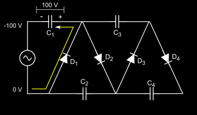 one side of the power supply is grounded and remains at zero potential, and the other varies between plus and minus U (100 V in the example). Here’s what happens:
- Capacitor C1 charges through diode D1 at the voltage U (100 V) of the power supply, which is at its negative peak. Note that this leads the capacitor to be positive at its right side and negative at its left. The yellow line indicates the direction of current flow
- We now have +100 V at the upper side of the
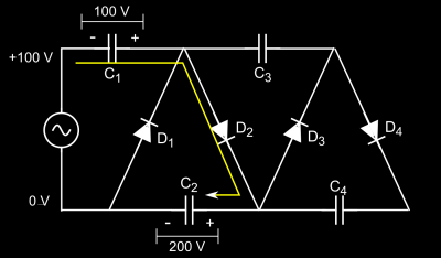 power supply, and this voltage adds to that of C1 that was charged in the previous step. Therefore capacitor C2 charges through D2 to 200 V, or 2U (100 V from the power supply plus 100 V from C2).
 - The charge stored in C1 was used in the previous cycle to charge C2, so C1 is now charging through D1 as in step 1. Also, capacitor C3 is charged through D3 to 2U.
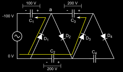 Why 2U? Because since C1 is discharged, point “a” in the schematic is at zero potential and C3 sees the 200 V of C2.
 - The power supply is again at its positive peak, and C2 is now being recharged as in step 2. At the same time, capacitor C4 charges to 200 V, because it is the potential difference that it sees: 400 V at its positive side (100 V of the supply plus 100 V of C1 plus 200 V of C3), and 200 V at its negative side, which is the
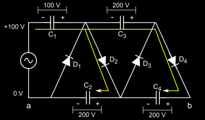 potential of C2.
As we can see, we will end with 400 V between ground and the output (points a and b in the last figure), effectively quadrupling the supply voltage.
This is an idealized explanation, and as you may guess reality is always more complicated. For instance, capacitors do not charge instantly, therefore they do not reach the full voltage until several cycles have passed, depending on the charging current that the power supply can deliver.
The multiplier that we just discussed has two stages. Each stage is formed by two capacitors and two diodes and each one adds two times the voltage of the power supply, so for example a five-stage multiplier will have an output of ten times the input voltage. Note that each component in the circuit only sees at most twice the peak input voltage provided by the source, therefore you can use low voltage components and many stages to obtain a very high output voltage.
 However, the output voltage will drop as soon as you connect a load to the circuit, according to this formula. Here we can see that we need high frequency and high capacitance in order to minimize voltage drop, and that this drop increases with current, and also very rapidly with the number of stages. In fact, since it depends on the cube of the number of stages, a multiplier with ten stages has 1000 times more voltage drop than one with a single stage.
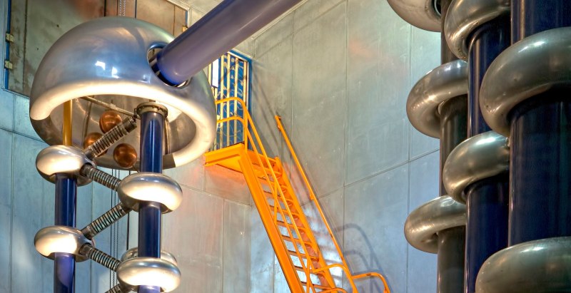
Another situation that arises when very high voltages are present is corona discharge, which is an electrical discharge that arises when the strength of the electric field around a conductor is high enough. Corona acts as an unwanted load on the multiplier, reducing the output power. One way to minimize corona is to reduce the curvature in conductors, avoiding sharp corners, projecting points and small diameter wires. For this reason large diameter end points and conductors are used. This of course complicates the design of very high voltage multipliers but at the same time accounts for their impressive look, as in the feature image.

The high voltage multiplier has a venerable history in particle accelerators, and even a Nobel prize in Physics was awarded for research that was possible thanks to it. However as new technology has arrived, in particular radio-frequency quadrupole systems, those magnificent multipliers have been retired. We sure will miss them, and of course that doesn’t stop you from building your own.



Try out yourself, I’ve built in Everycircuit:
http://everycircuit.com/circuit/5239629936852992
However the simulation doesn’t run in the Firefox browser, not in my installation anyway.
Dead-bugged voltage multipliers can be a really beautiful work of art!
Burned-out CFL lamps sometimes work as a power source. Don’t forget silicone wire and mineral oil.
Why so many diodes in the homemade V multiplier?
These are for very high voltages.
Most diodes (from the parts bin) have a break down voltage of 1KV or less.
So they put a few in series to use them for higher voltages.
Or you can take the diodes from old Micro wave ovens, but then you wil have to source 11 or more Micro wave Ovens.
If I put diodes in series, like 1N4001, for high voltage, I have to put 1M resistors in parallel with each diode so that one of them does not “run away” and take most of the voltage and self-destruct.
1N4007 would work better for that.
Only if the input frequency is 60 cycles or lower. For higher frequencies (and higher power) another high voltage fast diode is needed.
Not really needed. Diodes don’t instantly break from overvoltage, they start to leak some current first, and go into avalanche breakdown if the voltage keeps increasing. If a large current is allowed to flow (low source resistance), the dissipation (high voltage * high current) will destroy the diode.
However, if the total voltage is not shared evenly by several diodes in series, the diode with the highest voltage across it will start leaking more current than the others, thereby restoring the voltage balance, as the leakage current will cause the voltage across that particular diode to drop, while the voltage across the other diodes increases.
Of course, you do need to include some safety margin; using 10 diodes rated at 1kV each for a 10kV source would be bad; as soon as one of the diodes goes into avalanche breakdown, the voltage across it rapidly drops, and the voltage across the others increases as a result, until another one goes into avalanche breakdown, and soon everything will be on fire. For a 10kV source, I’d use 14-16 diodes in series, rated 1kV each.
Of course a safety margin is not bad, I would have chosen >=20%, of course 50% is also good. But “avalanche breakdown” does not mean that it behaves like a spark gap or DIAC. It behaves like a Z-diode, clamping the voltage.
a diode won’t self destruct it will just start to act like a zener and limit it’s voltage so the other in the string take over
A zener for 1,000 volts wouldn’t need much current to self-destruct! Diodes are rated for the FORWARD current and heat made with the forward voltage drop. A 1A diode dissipates 0.7 of a watt of heat at full capacity. That 0.7 of a watt is reached with 0.0007 of an amp when zenering at the 1,000 volts. If there’s a nice big cap in parallel when the diode decides to zener, you can guess what happens next. You get fireworks. :)
Jermaine, the leakage current of diodes is typically on the order of 10^-15 A. As long as all of them end up leaking less than 10^-14 A all will be fine.
As you say it’s the power that counts. So at 10^-11 W, the diodes are safe… :-)
Jermaine, there is no spark-gap like breakdown. The cap will limit the voltage rising speed and the diode will gradually start to conduct some current. It will even increase it’s breakdown voltage, when it gets hot. So there is no possibility that this cap could suddenly dump its charge into the diode.
A very easy to understand way to explain this circuit would be by a small video of the right kind of stairs/escalator/elevator.
Unfortunately I couldn’t find a yourtube vid.
The variant in my head was used a long time ago.
I consists of 2 ladders next to each other and they both move up and down 20cm to 1/2 a meter.
When one goes up, the other goes down & vice versa.
You move up (or down) by stepping from one of the ladders to the other at the right moment.
Does anyone know how this is called?
Youtube link?
Having built some excessively large multipliers stepping up from around 30Kv and able to throw a nice spark a good 200mm I found the best option was to drop the multiplier in transformer oil. I built an Ion Gun many years ago this way using an old automotive strobe light casing. The down side was the emitter was not far enough forward and given the trigger was just under 200mm from the emitter the first and last firing using the trigger was a little shocking.
One of the coolest uses however was to sit a small Z shaped rotor on the pin at the end with the unit sitting upright, turn it on and watch the rotor wizz around real fast as the negative ions were being flung off the points. then watch any dust in the room get sucked toward the casing.
In my early years as a radio ham, a circuit much like these were called bridge rectifiers. They let me get up to 900 to 1200 volts out of TV transformers intended to produce 450-600 volts.
https://en.wikipedia.org/wiki/Diode_bridge
This is actually closer to a half wave bridge than anything. If you look at the wikipedia article on the Cockroft-Walton Generator, you will see that you are actually looking at one half of the full multiplier. If driven with a true AC sine (with zero crossing), you are better off with the full wave variant.
(https://en.wikipedia.org/wiki/File:Full_wave_Cockcroft_Walton_Voltage_multiplier.png)
These actually do not have to be driven by a sine wave; a lowpassed square works equally well (although slightly less efficient in some cases)
Voltage multipliers used to be used in TV sets. A doubler to get about twice the peak line voltage for the horizontal output. Also sometimes another one at the output of the flyback to step up the voltage for the second anode of the CRT. I presume this was to reduce the cost of the flyback transformer.
Interesting, I always called ’em Cockcroft-Walton multipliers. While working on photomultiplier based cosmic radiation detectors headed for use out in space, we were having problems with noise caused by 1000V+ corona discharge in vacuum. The solution was a 10 stage C-W multiplier, with each stage supplying the 100 volt dynode to dynode drop in the 10 stage PhotoMultiplier tubes. The PM sockets were removed, and the C-W was fabbed directly onto the PM wires, then the whole shebang was primed and silicone rubber potted onto the tube. All the PM tubes were supplied with about 100VAC at 100KHz resulting in very small C-W capacitors needed. The 100VAC sine wave supply gave us no corona noise issues! We rode on the first satellites to leave Earth orbit. About a dozen years later, the one spiraling toward the Sun passed Earth, giving us another 100,000,000 miles of data! All 3 C-Ws were still cranking along. Huzzah! Huzzah! The C-W multiplier lives on in outer space!
Try explaining things like surface impedance, corona, and high voltage in general to current pcb manufacturers… Yeah, they just don’t get it.
So the higher the frequency of the AC input power the better? I wondered because these days solid state power amplifier chips can handle very high loads and high frequencies so a custom high frequency AC supply may not be that hard for a DIYer to do.
A car stereo power amp would work dandy. Find a suitable switching supply to power it, hook up a signal generator to the input, and you have the speaker output. Wire a normal transformer as step-up and add your multiplier. Normal transformers can handle audio frequencies, but as you jack up the frequency don’t get greedy. You’ll get eddy current heating and waste energy.
I use an old stereo + laptop as my high power signal generator all the time. They have built in overloads, easy to control output and if you blow a channel there are 1 – 3 spares depending on the model. Mine has happily driven everything from LEDs to a DIY foil/ribbon speaker.
5 million volt Russian voltage multiplier – would love to see in person. http://www.dailytech.com/Pictured+Drone+Survives+Flyover+of+Russias+Largest+Artificial+Lightning+Generator/article37172.htm
That’s only slightly horrifying (awesome).
My first helium-neon laser (in the 1960s) used a voltage multiplier in its power supply. It was a pain in the butt to get the lasing started, because the supply didn’t provide quite enough current.
It reminds me of Real Genius bridging the substation and “always check your optics”.
Good on you for getting things going with what you had :) and not turning us into popcorn.
oh lovely, reminds me of my days at ABB HVC. My first reaction when i first saw their test lab was, “OMG, they got tesla coils!”. Its “interesting” to do lightning/destructive tests on high voltage cables (as in cables that import/export power between countries).
http://abbcloud.blob.core.windows.net/public/images/95f07fe1-f78c-4c56-92ae-73dab104884b/Master.jpg
I see pictures of places like that and think to myself “How cool would it be to work there”. So was it or did the other things detract from the giant bug zappers?
It was very cool, especially moving around the small cable drums (~25 Ton) by hand.
also, cable cutting was a bit interesting.
(cant use my own pictures due to NDA so i am limited to whats publicly available)
http://www04.abb.com/global/seitp/seitp202.nsf/e308f3e92d9a8fc5c1257c9f00349c99/ca1a4ac2462c7494c1257960004baa6d/$FILE/_MG_4794%20cable%20factory%20300dpi.jpg
The orange things in the background is the “small drums”
http://www07.abb.com/images/librariesprovider51/jobba-hos-oss/examensarbete_1183x35089f536e3c1f463c09537ff0000433538.jpg?sfvrsn=1
A “big drum”
http://www04.abb.com/global/seitp/seitp202.nsf/0/943ab3f8e3fbab3bc1257c7c00484f5f/$file/Dudgeon+cables.jpg
sorry for all the pics/cable porn ;)
Dream job found! :D
Fun reading :) I leave the big stuff to the pros but love these break downs.
Great post, the one part I was hoping for was a comparison to a DC-DC charge pump. It is very similar, but you don’t need the clock with an AC input! I know, I know, wikipedia puts the diagrams side-by-side already.
I’m thinking this might be useful in bicycle generator circuits. Typically you have a generator rated at 6VAC, but depending on speed you get 5-7V. You can easily rectify and feed a linear regulator, but inefficiency in this application gets applied as resistance at the generator, which ends up meaning you pedal harder for the same speed! So efficiency is very useful here. So you want to use a DC-DC converter, but if you’re trying to get 5V out then a buck switcher is going to drop out pretty low. To get good performance you end up needing boost-buck or something, they’re all more complicated and lower efficiency than the straight buck.
The voltage multiplier shown here is also a rectifier, so it might be reasonable to use this to double the voltage, then only a simple buck switcher is needed and you have a low dropout voltage. I just learned on wikipedia that that is what that “120-240” switch on power supplies does; it converts the rectifier to a doubler!
This is more often used for high voltage, but there might also be a lot of utility in this circuit for the DIYer when dealing with low voltage AC!
The doubler will also introduce some inefficiencies: each diode will drop a minimum of 0.2 V (if you use Schottky diodes), for a start. Besides, at the low AC frequency of a typical bike generator, you will need hefty capacitors to power anything more demanding than a cycle computer.
What would be a good capacitance value, input AC frequency and load resistance to play with this circuit using an oscilloscope? Let’s say I’m using a function generator as the source of input AC voltage with amplitude up to 2 volts. I don’t want to “power” anything at the output end, I just want to see the voltage plots.
How we can improve the efficiency of voltage multiplier
is it ok to used it for low power application?? like with an input ac voltage of 2volts..
Might not work well at such a low voltage. Each diode drops about 0.7V to start conducting, not so? Something like 5V might be a more reasonable amount to play with.
i try this circuit in an actual and try to used a voltage regulator to have a good output signal, but i having experience a voltage drop within the V Mulitiplier and my expected output didn’t reached the expected output because of the drop in vmultiplier, how can we solve this problem to have a good output?? thank you
I built two CW voltage multipliers, one positive output and one negative output, and both driven from the same AC source, I know the voltage between the output terminals is twice what is normally possible with a single multiplier. Question: Will I damage the diodes or capacitors that are already rated at twice the input voltage? Should I build the CW multipliers with 4 times the input voltage rating i.e. use 20kv components if input voltage is 5kv or will 10kv parts be safe? Any engineering insight would be appreciated.
Was the 5kv input voltage rms, peak voltage, or peak-to-peak? You have to make sure the components can handle the peak to peak voltage of the input source. Most voltages are listed as rms, so 5kv rms = 7.1kv peak (RMS*√2=Vp), then multiply the Vp by 2 to get the Vpp, so you need at least 14.2kv rated components if your input voltage was 5kV rms.
How can I get the out put current?